3G3FV-PDRT1-SIN specifications
The Omron 3G3FV-PDRT1-SIN is a highly sophisticated variable frequency drive (VFD) designed to enhance energy efficiency and drive performance in various industrial applications. This particular model is part of the Omron 3G3FV series, which is well-regarded for its reliability, versatility, and ease of use.One of the main features of the 3G3FV-PDRT1-SIN is its ability to control asynchronous motors efficiently. The drive supports a wide range of motor types, making it suitable for diverse applications across different sectors, including manufacturing, HVAC systems, and material handling. The unit is designed to provide precise control over the speed and torque of motors, which is crucial for optimizing machine performance and energy consumption.
The 3G3FV-PDRT1-SIN incorporates advanced technologies such as vector control and high-performance algorithms. These technologies allow for superior motor control, enabling the drive to maintain accurate speed and torque under varying loads. This functionality is essential for applications that require consistent performance, particularly in processes that demand high precision and responsiveness.
Additionally, the drive features an easy-to-use graphical display, which simplifies the programming and monitoring of drive settings. Users can quickly configure the operating parameters and monitor performance metrics, enhancing operational efficiency. The intuitive interface also allows for quick troubleshooting, reducing downtime and maintenance costs.
The Omron 3G3FV-PDRT1-SIN is built with robustness and durability in mind. It conforms to several international standards, ensuring reliable operation in industrial settings. The drive is designed to withstand harsh environments, including fluctuations in temperature and humidity. This resilience helps to extend the lifespan of both the drive and the connected motor.
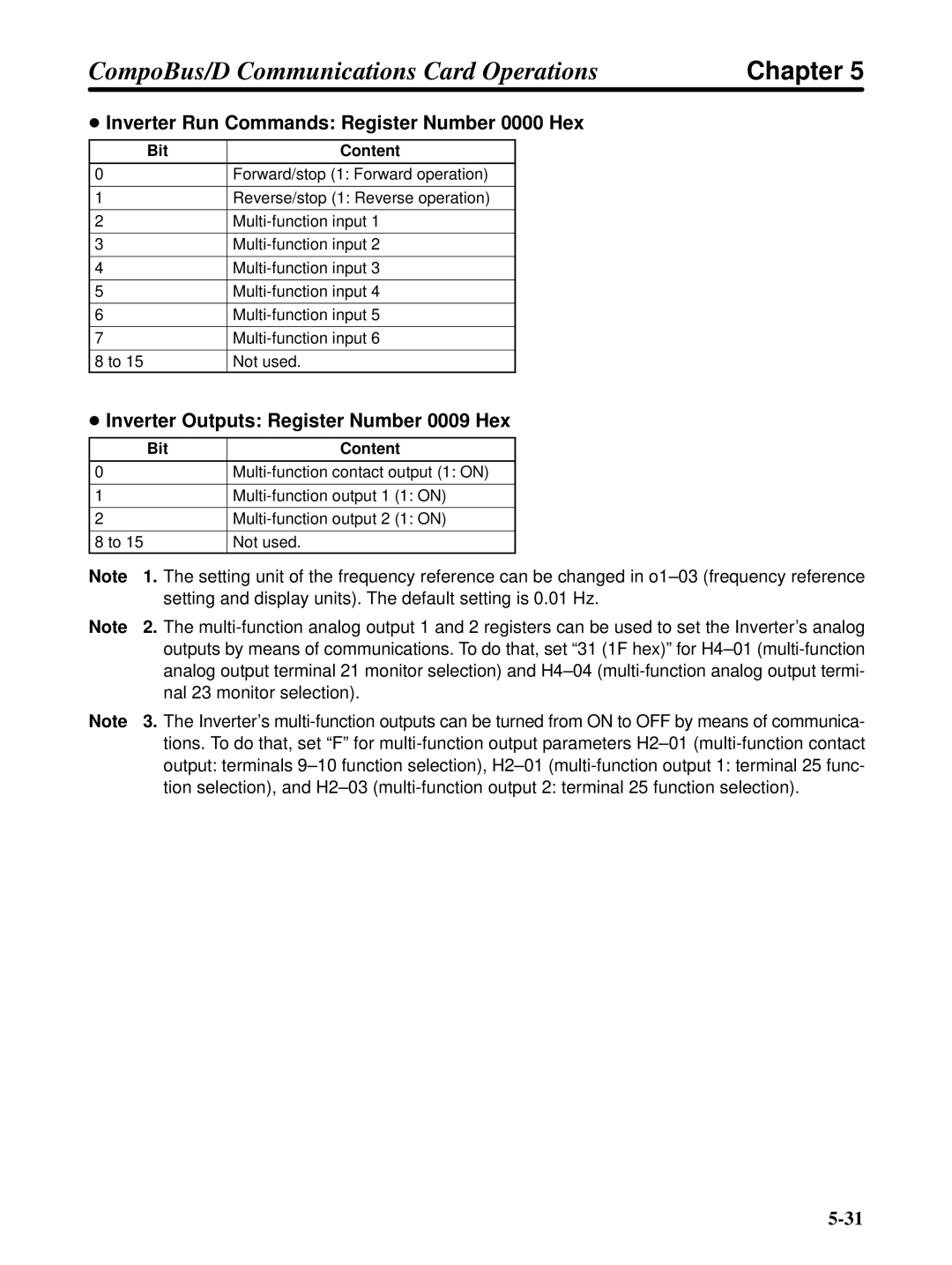
Furthermore, the 3G3FV series includes built-in communication capabilities that facilitate integration with other automation equipment. This connectivity supports various industrial protocols, enabling seamless data exchange and real-time monitoring of system performance.
In conclusion, the Omron 3G3FV-PDRT1-SIN is an advanced variable frequency drive that combines energy efficiency, precision control, and robust design. It is an ideal solution for optimizing motor-driven systems across a range of industrial applications, with features that enhance user experience and overall operational effectiveness.
