Setup (Initial Settings)
5 Set the LOCAL/MENU/REMOTE switch to the LOCAL or REMOTE position. The unit is now set to the menu protect mode.
When the LOCAL/MENU/REMOTE switch is set to the MENU position, “MENU PROTECTED” appears on the video monitor screen instead of the menu setting mode being established.
<Note>
If, while the menu protect menu is set, the LOCAL/MENU/REMOTE switch is set to the menu position while the front panel’s COUNTER button is held down, the menu setting mode will be established, and regular menu settings can be performed.
Perform steps 2 through 7 in “How to perform the settings using the
(See page 23)
How to release the menu protect mode
1 Set the LOCAL/MENU/REMOTE switch to the MENU position while holding down the front panel’s COUNTER button.
The unit is now set to the menu setting mode, and the menu screen appears on the video monitor.
2 Perform steps 2 and 3 of “How to initiate the menu protect mode” described above.
The screen to confirm whether menu protect is to be initiated or canceled now appears on the video monitor.
MENU PROTECT OK?
![]() NO
NO
YES
3 Press the
The menu protect mode is now released.
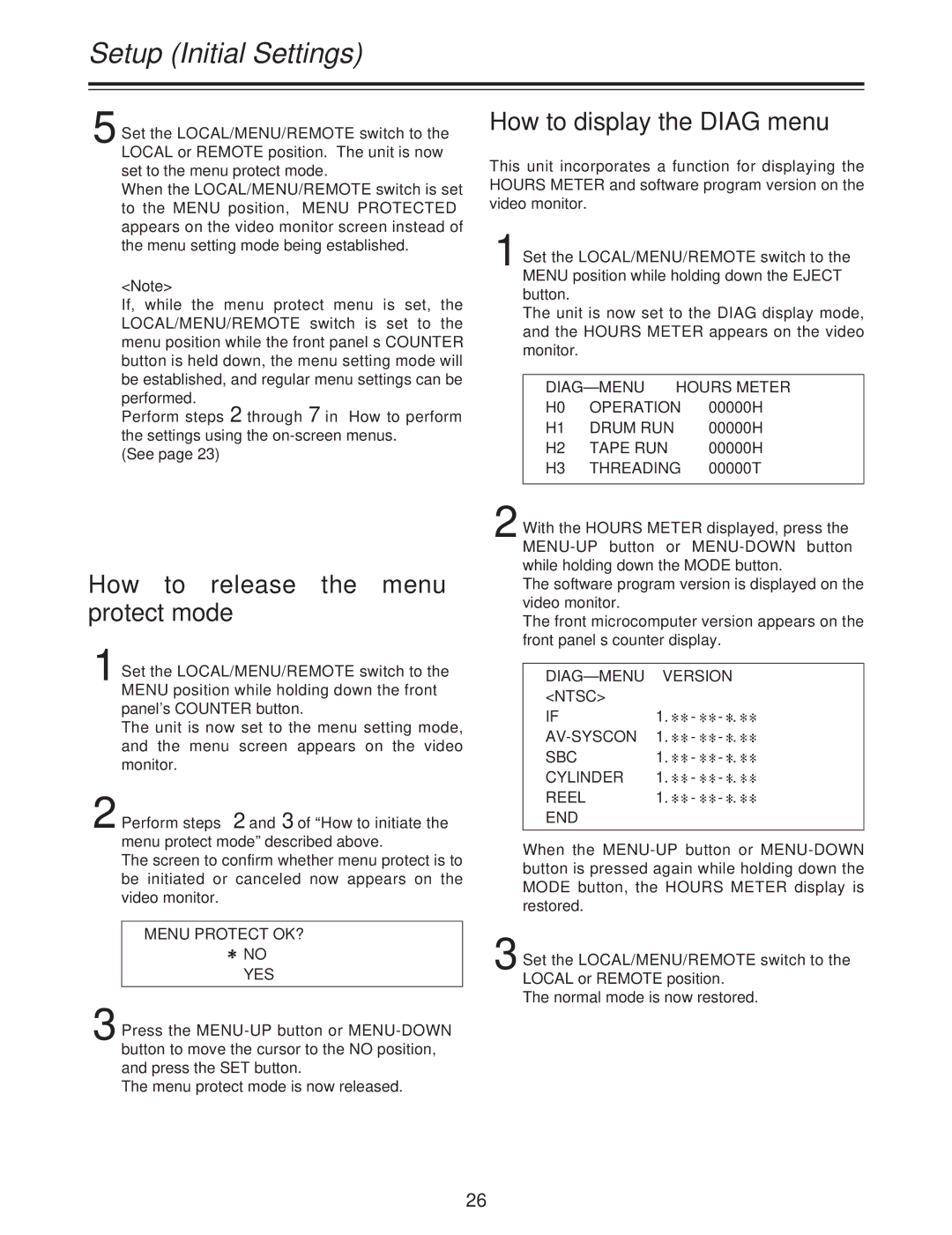
How to display the DIAG menu
This unit incorporates a function for displaying the HOURS METER and software program version on the video monitor.
1 Set the LOCAL/MENU/REMOTE switch to the MENU position while holding down the EJECT button.
The unit is now set to the DIAG display mode, and the HOURS METER appears on the video monitor.
H0 | OPERATION | 00000H |
H1 | DRUM RUN | 00000H |
H2 | TAPE RUN | 00000H |
H3 | THREADING | 00000T |
2 With the HOURS METER displayed, press the
The software program version is displayed on the video monitor.
The front microcomputer version appears on the front panel’s counter display.
| VERSION | ||
<NTSC> |
|
|
|
IF | 1. | - | |
| 1. | - | |
SBC | 1. | - | |
CYLINDER | 1. | - | |
REEL | 1. | - | |
END |
|
|
|
|
|
|
|
When the
3 Set the LOCAL/MENU/REMOTE switch to the LOCAL or REMOTE position.
The normal mode is now restored.
26
