Setup Menus
VIDEO menu
| Item |
| Setting |
| |
|
|
|
| Description of setting | |
No. | Superimposed | No. | Superimposed | ||
| |||||
display | display |
| |||
|
|
| |||
|
|
|
|
| |
|
|
|
|
| |
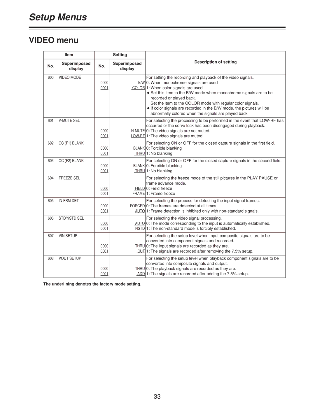
600 | VIDEO MODE |
|
| For setting the recording and playback of the video signals. | |
|
| 0000 | B/W | 0: When monochrome signals are used | |
|
| 0001 | COLOR | 1: When color signals are used | |
|
|
|
| OSet this item to the B/W mode when monochrome signals are to be | |
|
|
|
| recorded or played back. | |
|
|
|
| Set the item to the COLOR mode with regular color signals. | |
|
|
|
| OIf color signals are recorded in the B/W mode, the pictures will be | |
|
|
|
| abnormally colored when the signals are played back. | |
|
|
|
|
| |
601 |
|
|
| For selecting the processing to be performed in the event that | |
|
|
|
| occurred or the servo lock has been disengaged during playback. | |
|
| 0000 | 0: The video signals are not muted. | ||
|
| 0001 | 1: The video signals are muted. | ||
|
|
|
|
| |
602 | CC (F1) BLANK |
|
| For selecting ON or OFF for the closed capture signals in the first field. | |
|
| 0000 | BLANK | 0: Forcible blanking | |
|
| 0001 | THRU | 1: No blanking | |
|
|
|
|
| |
603 | CC (F2) BLANK |
|
| For selecting ON or OFF for the closed capture signals in the second field. | |
|
| 0000 | BLANK | 0: Forcible blanking | |
|
| 0001 | THRU | 1: No blanking | |
|
|
|
|
| |
604 | FREEZE SEL |
|
| For selecting the freeze mode of the still pictures in the PLAY PAUSE or | |
|
|
|
| frame advance mode. | |
|
| 0000 | FIELD | 0: Field freeze | |
|
| 0001 | FRAME | 1: Frame freeze | |
|
|
|
|
| |
605 | IN FRM DET |
|
| For selecting the process for detecting the input signal frames. | |
|
| 0000 | FORCED | 0: The frames are detected at all times. | |
|
| 0001 | AUTO | 1: Frame detection is inhibited only with | |
|
|
|
|
| |
606 | STD/NSTD SEL |
|
| For selecting the video signal processing. | |
|
| 0000 | AUTO | 0: The mode corresponding to the input is automatically established. | |
|
| 0001 | NSTD | 1: The | |
|
|
|
|
| |
607 | VIN SETUP |
|
| For selecting the setup level when input composite signals are to be | |
|
|
|
| converted into component signals and recorded. | |
|
| 0000 | THRU | 0: The input signals are recorded as they are. | |
|
| 0001 | CUT | 1: The signals are recorded after removing the 7.5% setup. | |
|
|
|
|
| |
608 | VOUT SETUP |
|
| For selecting the setup level when playback component signals are to be | |
|
|
|
| converted into composite signals and output. | |
|
| 0000 | THRU | 0: The playback signals are recorded as they are. | |
|
| 0001 | ADD | 1: The signals are recorded after adding the 7.5% setup. | |
|
|
|
|
|
The underlining denotes the factory mode setting.
33