Operating Instructions
Safety precautions
FCC Note
Important Safety Instructions
Contents
System settings
Input/output signal settings
Setting the multi view display
External device control interfaces
Before use
Overview
Characteristics
Display of camera information
Switching of materials
Control using PAN/TILT lever and Zoom button
Transmission of tally information
Accessories
Required personal computer environment
Operating precautions
Parts and their functions
Control panel
OSD on button OSD on
Shift button Shift
OSD/TIME dial OSD/TIME
PinP on button PinP on
Slide lever
Bus tally indicators A, B
Auto button Auto
MIX button MIX
Bus crosspoint buttons 1 to
While the indicator of the KEY-F/S button is lighted
Memo
SDI in connectors SDI in 1 to
Power switch Power
SDI OUT connectors SDI OUT 1
DVI in connector DVI
Cooling fan DC in connector 12V in DC 12V, 2.5A
DVI OUT connector DVI OUT
LAN connector LAN RJ-45 10BASE-T/100BASE-TX
Ground terminal Signal GND
Installation precautions
Preparations
Block diagram AW-HS50
Connections with other devices
Example of connections
Compact Live Switcher
AW-HS50
HUB
Set the Power switch to the OFF position
Turning the unit’s power on and off
Set the Power switch to the on position
Checking the video output
Displaying the OSD menus on an SDI monitor
Turn off the power of the unit
Changing the video format
OSD on-screen display menu operations
Changing the connector for outputting the OSD menus
How to forcibly display the OSD menus
Displaying and clearing the OSD menus Basic operations
Submenu
Moving between the main menu and submenus
Main menu
Moving from the main menu to a submenu
Changing the setting
Operations using the submenus
Selecting the line with the setting item
Returning the setting to its default value
Moving the blinking area
Wipe Menu Submenu Adj Border Col Setting item
Indications used in these instructions
Completing the changes
Basic operations
Select the bus using the Shift function
Assigning signals to the crosspoint buttons
Background transitions
Selecting the transition type
Selecting the bus mode
Manual transitions
TIME/CBGD Menu Auto Time
Auto transition
Cut transition
Operation Menu Time Unit
Selecting the wipe direction
Setting the border width and soft effect
Wipe
Selecting the wipe pattern
Adjusting the border color
Setting the border color
Registering and recalling the preset memories
KEY
Setting the PinP and KEY priority
Concerning key combinations
Selecting the key materials
Setting the transition duration TIME/CBGD Menu KEY Time
Key transition
Fill
Key setup
Key Type
Set Fill Col
Adj Edge Col
Edge Type
Set Edge Col
Edge Direction
Clip
Key adjustments
Mask Adjust1, Mask Adjust2
Gain
Marker Pos
Chroma key adjustments
Maker
Sample
Marker Aspect
Ref Adjust
Cancel
Influence
Selecting the PinP material
Setting the transition duration TIME/CBGD Menu PinP Time
PinP picture in picture
PinP transition
PosX/Y/Size
PinP settings
Shape
Border Width
Trim Adjust1 item
Trim Adjust1, Trim Adjust2
Set To Preset
Trim Adjust2 item
Transition between PinP materials
Effect dissolve
Selecting the Dot by Dot mode
Input Menu Mode Normal
DbyD
FTB fade to black
Internal color signals
Color Adjust
Cbgd Color
Selecting the AUX bus material
Switching the AUX output
Select the output signal using the a bus crosspoint buttons
Transitions between AUX materials
Displaying the chroma key markers
Setting the User buttons
Displaying the 5 KEY Adjust Menu submenu
Displaying the 3 PinP Menu submenu
USER/FMEM Menu Fmem Select
Frame memories
Transferring images from the AUX bus
USER/FMEM Menu AUX to Fmem Rv Review
Saving images in the flash memory
USER/FMEM Menu Fmem Mode
Ex Exec
Input signal settings
Input/output signal settings
List of settings by input signal
Setting the input mode
Setting the material name type
How to set the material names
Setting the material names
Setting the freeze method
Frame
Setting the up-converter
Freezing and canceling the freezing of the input images
Setting the video process function
Input Menu/SDI-IN3 UCScale/ECPos Input Menu/SDI-IN4
Input Menu/SDI-IN3 UCMvdet/Sharp Input Menu/SDI-IN4
Setting the input image scaling
Resolutions supported
Input Menu/DVI-IN Scale
Table of DVI input scaling sizes
1600
1680
1920
Input Menu/DVI-IN Size Freq Dot Clock
Displaying the input image information
DVI-D formats supported
Setting the color areas
Setting the output signals
Assigning the output signals
Setting the DVI-D output signals
Output Menu DVI-OUTScale
Output Menu DVI-OUTMvdet
Setting the multi view display
Screen layout
Setting the split frames and characters
Setting the tally displays
Setting the level meters
Setting the input signal marks
Setting the video format
System settings
System menu settings
How to specify the video format and then start the system
Setting the ancillary data
Network settings
System initialization
Operation Menu OSD Size
Operation menu settings
OSD on-screen display settings
Operation Menu OSD Back
Other settings
Bus status displays
Version displays
Sub 15-pin, female, inch thread
External device control interfaces
LAN connection
Example of an open collector output connection
Image transmission functions
Connections with a computer
Connections
How to install the software
Startup
Setting the IP address
Basic operations of software
Exit
Image transfer
Transferring images from the computer to the unit
Transferring the unit’s images to the computer
Transferring the setup data to the unit
Transferring the setup data from the unit
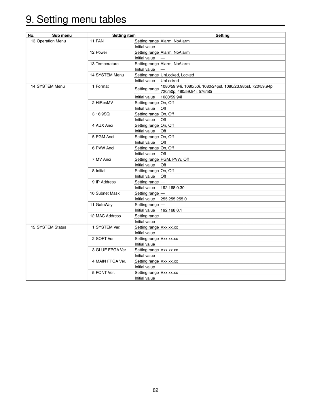
Setting menu tables
Sub menu Setting item
KEY Setup Menu KEY Adjust Menu ChromaKey Menu
XPT1
SDI
SQ, EC, LB
SDI-OUT1
FAN
Sub menu
Appearance
Unit mm inch
Specifications
Control I/O
Video delay time
DVI-D output
Other
Supplied power cord
Temperature Humidity
Power supply
Dimensions
Appendix glossary
General Purpose Interface Hue
Preset Bus
Setup Data
Key Edge
Trimming
Transition
Tri-level Sync
Up Converter
F0410Y0
Operating Instructions Basics
this Apparatus Must be Earthed
Important Safety Instructions
Appearance Specifications
Concerning the ratings display
Disclaimer of warranty
Characteristics
Parameter operation using PAN/TILT lever and Zoom button
CD-ROM
Concerning the consumable parts Cooling fan
POWER indicator Power LINK indicator Link
Alarm indicator Alarm
OSD/TIME dial OSD/TIME
User buttons User 1, User
Shift button Shift
OSD on button OSD on
CUT button Bkgd CUT
KEY on button KEY on
FTB on button FTB on
Auto button Bkgd Auto
Wipe button Wipe
Bus tally indicators A, B
MIX button MIX
BUS Delegation buttons AUX, PinP, KEY-F/S
While the indicator of the KEY-F/S button is blinked
While the indicators of all three buttons are off
While the indicator of the PinP button is blinked
Memo
SDI in connectors SDI in 1 to
Power switch Power
SDI OUT connectors SDI OUT 1
DVI in connector DVI
Cooling fan DC in connector 12V in DC 12 V, 2.0 a
DVI OUT connector DVI OUT
LAN connector LAN RJ-45 10BASE-T/100BASE-TX
Ground terminal Signal GND
Preparations
Block diagram
AW-HS50
Compact Live Switcher AW-HS50
AW-HE50S
Turning on the power
Turning off the power
Changing the video format
OSD on-screen display menu operations
Displaying and clearing the OSD menus Basic operations
USER button status display
Moving between the main menu and submenus
Displaying menus consisting of more than one
Select the line with the setting item
Change the setting
Move the blinking part
Indications used in this Operating Instructions
Complete the changes
Direct operations using the User buttons and OSD/TIME dial
Example When 2 Wipe Menu is displayed
Menu delegation function
List of menu delegation functions
67 2-5/8 53 2-1/16
DVI
High-resolution multi view mode supported
Current consumption
Power requirements
Supplied AC adapter
H D
F0610Y1070 D