COMSPHERE 3821Plus Modem
|
|
| STANDOFF |
|
| P24 |
|
P26 | P25 | P20 P19 | P23 |
| |||
|
| ||
J2 | P22 | J1 | P21 |
TO P23
OR P25
TO P24
OR P26
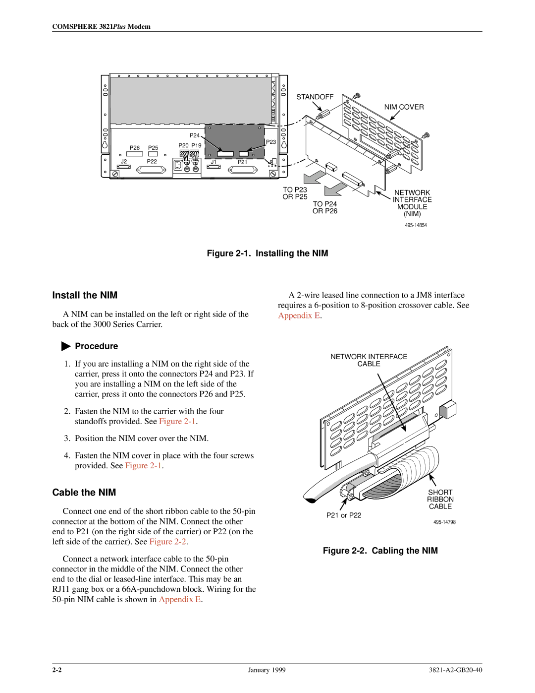
Figure 2-1. Installing the NIM
NIM COVER
NETWORK INTERFACE MODULE (NIM)
Install the NIM
A NIM can be installed on the left or right side of the back of the 3000 Series Carrier.
"Procedure
1.If you are installing a NIM on the right side of the carrier, press it onto the connectors P24 and P23. If you are installing a NIM on the left side of the carrier, press it onto the connectors P26 and P25.
2.Fasten the NIM to the carrier with the four standoffs provided. See Figure
3.Position the NIM cover over the NIM.
4.Fasten the NIM cover in place with the four screws provided. See Figure
Cable the NIM
Connect one end of the short ribbon cable to the
Connect a network interface cable to the
A
NETWORK INTERFACE
CABLE
SHORT
RIBBON
CABLE
P21 or P22
Figure 2-2. Cabling the NIM
January 1999 |