COMSPHERE 3821Plus Modem
Install the Circuit Card
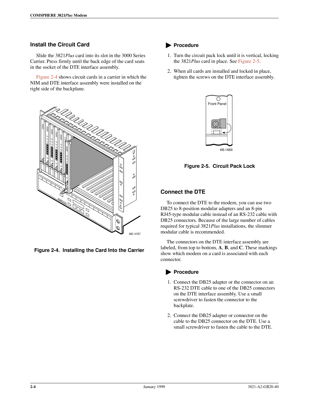
Slide the 3821Plus card into its slot in the 3000 Series Carrier. Press firmly until the back edge of the card seats in the socket of the DTE interface assembly.
Figure 2-4 shows circuit cards in a carrier in which the NIM and DTE interface assembly were installed on the right side of the backplane.
Figure 2-4. Installing the Card Into the Carrier
"Procedure
1.Turn the circuit pack lock until it is vertical, locking the 3821Plus card in place. See Figure
2.When all cards are installed and locked in place, tighten the screws on the DTE interface assembly.
Front Panel
Figure 2-5. Circuit Pack Lock
Connect the DTE
To connect the DTE to the modem, you can use two DB25 to
The connectors on the DTE interface assembly are labeled, from top to bottom, A, B, and C. These markings show which modem on a card is associated with each connector.
"Procedure
1.Connect the DB25 adapter or the connector on an
2.Connect the DB25 adapter or connector on the cable to the DB25 connector on the DTE. Use a small screwdriver to fasten the cable to the DTE.
January 1999 |