CM6800E-48X8
Contents
Control Genex Multiplexer and Genex Multiplexer Displays
List of Illustrations
List of Tables
C1528M-F 6/05
For Qualified Service Personnel only
Important Safeguards and Warnings
Sample CM6800E-48X8 System
Description
Sample CM6800E 96 x 16 System
Keyboards
Sequences, Macros, Presets, Patterns, and Zones
System Access and Priority
Programming
Continuous Operating Device
Alarm Inputs
Power, Mounting Methods
Auxiliary Outputs
Associated Equipment
Models
Compatible Products
Additional Resources
Mounting
Installation
Main unit Cameras Expansion unit Cameras
96 x 16 System Default Camera Numbers
Video Sources
Cable Type Maximum Distance
Connecting Looping Video Sources
96 x 16 System PTZ Control Capacity
Control Lines
96 x 16 System Monitor Capacity
Monitors
Main unit Monitor Expansion Unit Monitor
96 x 16 System Alarm Capacity
Alarms
Main unit Alarms Expansion Unit Alarms
Input Type Wiring Pin-Outs Default Device
Connecting Devices Through the Communication Ports
CM9760-MDA, Ascii
RS-485, 19200 baud, no parity, 8 data bits, 1 stop bit
RS-485 Pin-Outs Ascii device CM9760-MDA, Satellite Rx+
Ground Tx+ RS-232 Pin-Outs RJ-45
Port
CM6800E Communication Port Connections and Options
KBD100, KBD200A, and KBD300A Series Keyboards
KBD100, KBD200A, and KBD300A Direct-Powered Keyboards
OFF
Keyboard Address Switch Settings
Table E. Switch Settings-KBD200A/300A Keyboards Only
Keyboard Switch
Remote Keyboards
KBD100, KBD200A, and KBD300A Remote Keyboards
Devices Addressing
Devices KBD960, ALM2064, REL2064
KBD960/KBR960 REL2064 ALM2064
Connecting a KBD960/KBR960 to the CM6800E
Connecting a Single KBD960/KBR960 Keyboard
To connect a single ALM2064 Alarm Interface Unit
Connecting a Single ALM2064 Alarm Interface Unit
To connect a single REL2064 Relay Interface Unit
Connecting a Single REL2064 Relay Interface Unit
Multiple M Devices Local Connection
Multiple M Devices
Multiple M Devices Remote Connection
Connecting Multiple M Devices Remote Connection
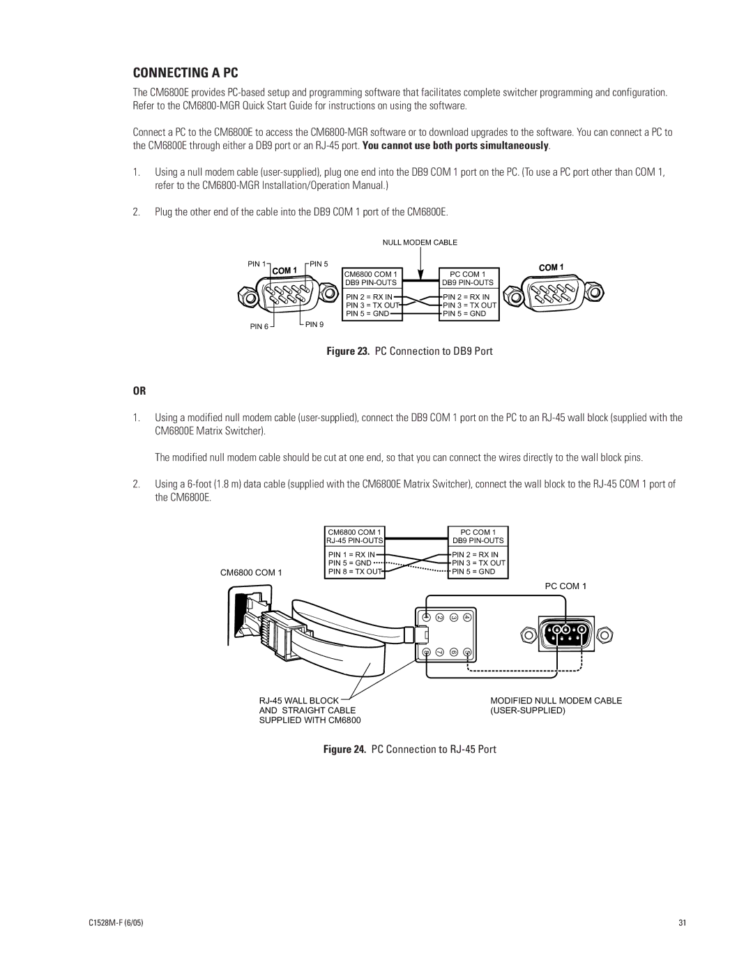
PC Connection to RJ-45 Port
Connecting a PC
Connecting Genex Multiplexers
Connecting Genex Multiplexers
Main unit AUX Expansion Unit AUX
Connecting Relay Contacts AUX 1
Local Auxiliaries
96 x 16 System Auxiliary Capacity
Wiring the F3 TTL Output
Connecting the Open Collector Output F3 TTL
CM6800E-48X8 Main Unit
Connecting a 96 X 16 System
System START-UP
POWER-UP the System
Initialize Keyboards
COM
Configure the System
Port Default Settings
Communication Ports
Control MUX
96 X 16 System Settings
KBD960/KBR960 Keyboard
Genex Multiplexer
Program Presets
Monitor Color Adjustment
Additional Programming
Programming the CM6800E
Exit Programming Mode
CM6800E Programming Mode
Select Language
Function
Entries in Programming Mode
Keyboard
Navigate to the Next or Previous field Press F1
Navigate to the Help field Press F1
Camera to Monitor
Access
Keyboard to Monitor
Camera to Keyboard
Program Alarm Groups
Alarm Programming
Program AN Internal or External Alarm Contact
Priority
AUX field, select an auxiliary to be activated
ACK Type
Type
Program Video Loss Alarms
Program a Video Loss Alarm
Assign a Logical Alarm Number
Assign a Logical Alarm Number Optional
Latching or Momentary Operation
Alarm-based Operation
Mode field for each auxiliary, select either LAT or MOM
Auxiliary Outputs
Program Logical Numbers
Camera Programming
If necessary, first program logical camera number
Program Cameras
Select Character
Program Vertical Drive Option Optional
Event Timers
Macro Status View Screen
Macros
Type Display Values
Monitor Display
Monitor
Camera Title
Date
Monitor Status Display Values
ALM Status Display Values
Time
Use the Set Password screen to change the system password
Password
Serial Port Input on CM6800E rear panel
Ports SERIAL/COM Ports
Action Ascii text
Level 1 = highest priority Level 8 = lowest priority
Priority
Port
Options
Change the System Setting
96 X 16 System Settings
Sequence
Sequences
Turn camera auxiliary on
AUX and ##
Turn global auxiliary on
Turn global auxiliary off
Time and Date
PATTERNS, PRESETS, and Zones
Options DD/MMM/YY MMM/DD/YY YY/MMM/DD DD/MM/YY YY/MM/DD
Operating the CM6800E
Switch Monitors
Operation
Overview
Control Receivers
To move through the sequence one camera at a time
Operate Sequences
Select Macro to start the macro
RUN a Macro
Select To start the macro
Call a Preset
Acknowledge AN Alarm
Patterns are not available with the KBD100 keyboard
Create and RUN a Pattern
Operate an Auxiliary in a Receiver
Operate AUXILIARIES/RELAYS
Operate a Local Auxiliary
Operate an External Auxiliary
Define Zones
Control Genex Multiplexer and Genex Multiplexer Displays
Operate Scanning Functions
Detect Video Loss
Appendix
CM6800E DIP Switches
CM6800E DIP Switch Default Setting
Switch
Chronological Pair D and Q
Alarm Group Display Options
Monitor Alarm Alarms
Block Build
Reverse Chronological Pair M and L
Monitor Alarm Alarms Next Display Cycle
Salvo Group
Description Specify Fields
Macro Commands
Auxiliary Notes
HEX
Pipo
Quad
Nano
Install the CM6800E AS a Satellite Device
Page
Satellite Monitor Access
Configure the CM6800E AS a Satellite Device
Change the Port Setting
Satellite Port Settings
Enable Alarm Contacts
Satellite Alarms Optional
Add a Satellite Device in the CM9700-MGR
Configure CM9700-MGR System Manager Settings
Configure CM9760-MGR System Manager Settings
Click the Comms tab. The Comms page appears
Program the Comms File
Click the Cameras tab. The Cameras page appears
Program the Cameras File
Click the Link Cameras tab. The Link Cameras page appears
Program the Link Cameras File
Click the Alarms tab. The Alarms page appears
Program the Alarms File Optional
Click OK to close the Alarm Camera Switches dialog box
Press 89 Preset
How to Display the CM6800E Programming Main Menu
How to Exit Programming Mode
How to Select a Numerical Value in an Option Field
Link Camera Name
Logical Number Assignment Table for Link Cameras
Link Camera page Phy Num column
Functional Procedure Commands Result
Ascii Operating Commands
3Ma16#a
Uppercase characters
Desired Action Command Result
Logical Alarm Number in the Alarm Programming section
48~Jva Trigger an alarm #Ea
Clear an alarm #Ia
Acknowledge an alarm #Ka Panel An alarm is triggered #Ea
Gaining Initial Control
Troubleshooting
Wait AT Least Five Seconds
Dip Switch Cover Plate
Software Reset
Problem Remedy
Solutions to Common Problems
Icon/Button Legend
KBD960/KBR960 ICON/BUTTON Legend
Upgrade the CM6800 Switcher Software
Upgrade the CM6800 Switcher Software
Term Definition
Glossary
Ascii
PAL
Ntsc
PTZ
Recommended distance is 4,000 feet 1,219 m
All four wires
Star configuration
RS-422
Specifications
48 x 8 System
Regulatory Notices
96 x 16 System
Product Warranty and Return Information
C1528M-F 6/05 105
ISO9001