Table of contents
Disc Manager DM
Access control Child Lock
Glossar Remote control codes
User preferences for the HDD
Overview of functions
Functioning of the device
Remote control
CAM1 / Video CAM1 , DV in CAM2
English
Additional TV functions
Yellow socket
Front of the device
Behind the flap at the right corner on the front
White/red socket Audio R CAM1 Audio input socket left/right
Output sockets Digital Audio OUT
Back of the device
Output sockets AUDIO/VIDEO OUT
Output socket G
Recording and playback
Introduction
Discs you can use
Playback only
Regional code
Technical data
Accessories
Alaser
Can I use a CD lens cleaner in the DVD recorder?
Symbols used in these operating instructions
Cleaning the discs
Therefore, refrain from using a CD lens cleaner disc
Special functions of your DVD recorder
Introduction
Model NO. Hdrw 720/00-02 PROD. no
Connecting the DVD recorder
Preparing the remote control for operation
Using your DVD remote control With your TV set
Connection with scart cable
Connecting to the aerial
Connecting to the TV
Several scart sockets on the TV?
Connection with an S
Connection with video Cvbs cable
Connection with the aerial cable only
Connecting to the mains
Switch on the TV set
Connecting an external receiver
Connecting additional devices
Connecting additional devices to the second scart socket
Connecting a video recorder, DVD player
Digital DV input socket
Connect camcorder to the front
Aerial cable Sockets
Socket
Can I use the Phono input on my amplifier?
Connecting audio devices to the analogue audio sockets
Connecting audio devices to the digital audio sockets
Digital multi-channel sound
Installation
Initial installation
Letterbox
What is the subtitle language?
Why do I have to set the country?
Panscan
Using a satellite receiver
Sound may be distorted on some TV channels
EXT2
Manual TV channel search
Additional installation features
Allocating a decoder
For and store the missing or coded TV channels manually
TV channel name, press C
Cannot switch my TV set to programme number
Sorting TV channels automatically Follow TV
Nicam
Switch off recorder, new preset appears on the screen
Automatic TV channel search
Will appear in the display
Deleting TV channels
Setting the language
Sorting and deleting TV channels manually
Audio Language
Setting the time
Time/date is displayed incorrectly despite manual setting
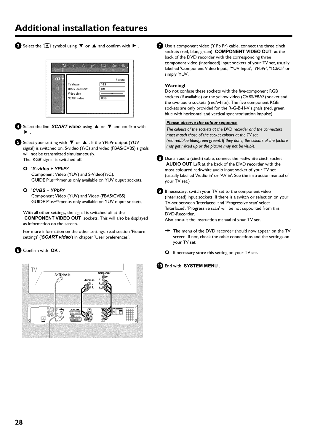
Please observe the colour sequence
Video + YPbPr
Cvbs + YPbPr
0End with System Menu
Guide Plus+ System
General information Setting up the Guide Plus+ System
Setup
Time and date must have been set
Country
Installation of the External receiver
Language
Postal code
My external receiver is connected only via aerial cable
Connecting G transmitter
My brand is not included in the list
How do I find the right position?
Want to install additional external receivers
Finalise set
My external receiver does not display the programme number
Using the Guide Plus+ System
General
Navigation in the Guide Plus+ System
Grid screen
Function buttons colour buttons in the Grid screen
Choosing a TV channel from a listing
Search screenThe Schedule screen
Function buttons colour buttons in the Search Screen
Function buttons colour buttons in the Schedule Screen
Info screen
Setup screen
Setup
Editor screen
What is the advantage from 1 hour and 6 hours?
Recording on the HDD
General Time shift Buffer
Symbols in the Time Shift Buffer
Navigation in the time shift buffer
Mark TV shows for recording
Mark part of a title
Manual recordings
OTR recordings
Auto delete
Switching Direct Record on or off
Automatic recording from a satellite receiver sat recording
Direct Record
Please observe
Recording from a video recorder/DVD player
Recording from a camera connected to the front sockets
Please observe the following
You can stop the recording using the following buttons
Pause
Stop h
Programming a recording Timer
General
Programming recordings with the Guide Plus+ System
Programming recordings with the ShowView System
Programming recordings without the ShowView System
Frequency Green function button
Changes using the colour buttons
Selecting a TV channel from the listing
Activate VPS/PDC Timing Yellow function button
Cancel a programmed recording in progress
Search by time
Additional playback features
Playback from the HDD
Repeat
Zoom feature
Symbols in the Media Browser
Media browser
Change title settings
Change order for the media browser
Change the name of the title
Edit title
Title name
Clear chapters
Enter characters using
Editing recorded titles name Divide title
Select
Insert chapter markers
Press Pause Press OK . The marker will be inserted
Remove chapter marker
Archiving of the edited title
Hide chapters sections
Chapter is visible and can be hidden with the blue button
Hidden szenes were not copied on the DVD+RW/+R
Recording on a DVD+RW/+R
Archiving storing titles on a
Protect disc against accidental recordings
General notes on playback
Switch over to the actual TV channel during Playback
Playback from a disc
Inserting a disc
Playing an audio CD
When creating MP3 CDs please note the following
Playing a DVD+RW/ +R disc Playing an MP3 CD
Important notes for playback
Playing a Super Video CD
Still picture
Additonal playback features
Searching a disc
Slow motion
Repeating a passage a
Repeat/Shuffle play Scan feature
Search by time
Time entered will flash on the screen
Camera angle
Zoom feature
F symbol will be hidden
Select the audio language
Managing the disc contents
Deleting chapter markers
Switching quickly
Hiding chapters
Numbers
How can I select different chapters?
Changing the index picture
Dividing titles
Can I divide titles on DVD+R discs?
Playing the entire title
You can delete the character using the red function button
Editing recording titles name
How can I enter the characters with the buttons 0..9 ?
Changing the disc name
Erasing recordings/titles Disc settings
Select Erase this title using a or B and confirm with OK
Can titles be deleted from a DVD+R disc?
Finishing editing
Finalising DVD+R discs
Erasing DVD+RW Discs
Disc Manager DM
General information Adding a disc to the Disc Manager
Removing discs from the Disc Manager
Searching discs
Searching for a title in the Disc Manager
Zoom
User preferences for the HDD
Audio
Time search
Chapters
Record mode
Camera mode
HDD buffer
Filter
Safety Slot
Direct rec
Jump forward
Follow TV
Installation
Flush Buffer
Time/Date
Picture settings
Additional user preferences
Digital output
Sound settings
Night mode
Analogue output
Language settings
Additional settings
Auto resume
Disk feature menu
Access control
Finalise disc
Activating/deactivating child lock
Access control Child Lock
Child lock DVD and VCD
Authorising a disc
Parental level control DVD video only
Confirm Access control using C
Confirm with OK . Quit using D and System Menu
Activating/deactivating parental level control
Changing the PIN code
Have forgotten my code
Field for temporary messages
Symbols in the menu bar
Information on the screen of your TV
Status field
Symbols on your DVD recorder display
Messages in the DVD recorder display
An empty title on a DVD+RW/+R is selected
Before you call an engineer
OPEN/CLOSE J
BImportant
Before you call an engineer
Press GUIDE/TV
DVD+RW disc cannot be played on certain DVD players
Index screen flickers when a DVD+R is inserted
BYou can finalise the disc using the following function
Glossar
Ntsc
PAL
Remote control codes
Finlux 208, 209, 211, 212, 250 333, 334 332 283
MGA
English Deutsch
3103 605 4174/000
Technical data
Hdrw 720/00
Philips Norge AS Philips PORTUGUESA, S.A