02Connecting up
Chapter 2
Connecting up
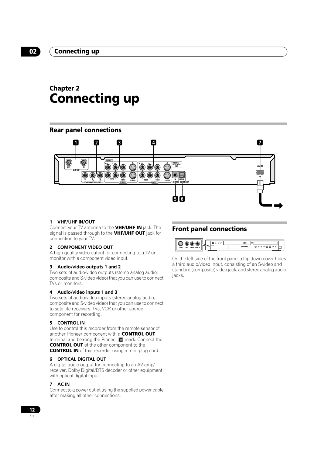
Rear panel connections
1 | 2 | 3 | 4 | 7 |
OUTPUT 1
R | L |
OUTIN
VHF/UHF
Y | PB | AUDIO |
PR |
COMPONENT VIDEO OUT
| R | L |
VIDEO | AUDIO |
OUTPUT 2
INPUT 1/ |
|
AUTO START | AC IN |
REC |
VIDEO
INPUT 3 | CONTROL DIGITAL OUT |
5 6
1 VHF/UHF IN/OUT
Connect your TV antenna to the VHF/UHF IN jack. The signal is passed through to the VHF/UHF OUT jack for connection to your TV.
2 COMPONENT VIDEO OUT
A
3 Audio/video outputs 1 and 2
Two sets of audio/video outputs (stereo analog audio; composite and
4 Audio/video inputs 1 and 3
Two sets of audio/video inputs (stereo analog audio; composite and
5 CONTROL IN
Use to control this recorder from the remote sensor of another Pioneer component with a CONTROL OUT terminal and bearing the Pioneer mark. Connect the CONTROL OUT of the other component to the CONTROL IN of this recorder using a
6 OPTICAL DIGITAL OUT
A digital audio output for connecting to an AV amp/ receiver, Dolby Digital/DTS decoder or other equipment with optical digital input.
7 AC IN
Connect to a power outlet using the supplied power cable after making all other connections.
Front panel connections
![]()
On the left side of the front panel a
12
En