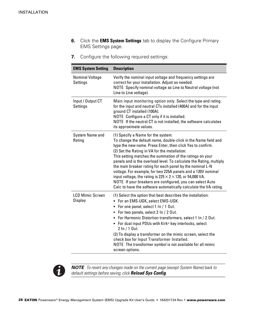
415/240V, 380/220V, 208/120V, 400/230V specifications
The Powerware series of uninterruptible power supplies (UPS) is renowned for its versatility and reliability in providing essential power protection for critical equipment across various environments. Specifically, the configurations of 208/120V, 400/230V, 380/220V, and 415/240V cater to a wide range of geographic voltage standards, making it an ideal solution for diverse industrial and commercial applications.One of the defining features of the Powerware UPS is its robust architecture which ensures high availability and reliability. Designed for mission-critical environments, these units often come equipped with advanced technologies that facilitate seamless operation during power interruptions or fluctuations.
The Powerware UPS employs double-conversion online technology that offers superior protection by continuously converting incoming AC power to DC and then back to AC. This process isolates the connected equipment from all power disturbances, such as surges, sags, and electrical noise, thus ensuring clean and stable output power. With this technology, users can rest assured that their sensitive electronics and IT infrastructure are shielded from any potential damage caused by irregular power supply.
Additionally, the Powerware series includes intelligent battery management systems that extend battery life and optimize performance. This feature involves real-time monitoring of battery health and automatic adjustment of charging methods to enhance efficiency. Users benefit from reduced maintenance costs and increased operational uptime due to improved battery management.
Moreover, the Powerware UPS is designed with scalability in mind. These units can be configured in parallel for load sharing, allowing organizations to expand their power capacity as needed without having to invest in entirely new systems. This flexibility is particularly beneficial for growing businesses that anticipate increased power needs over time.
The compact design and enhanced cooling systems further characterize the Powerware UPS, making it suitable for installations in space-constrained environments. The units are often equipped with user-friendly interfaces, providing easy access to critical information and diagnostics for power management.
In summary, the Powerware series with 208/120V, 400/230V, 380/220V, and 415/240V configurations represents a comprehensive solution for ensuring uninterrupted power supply in various settings. Its advanced technology, battery management features, scalability, and space-saving design make it an excellent choice for organizations seeking reliable power protection.

