RAD Data Communications Headquarters US East US West
LRS-24
Order from Cutter Networks Ph727-398-5252/Fax727-397-9610
Warranty
Ports Safety Status
Safety Warnings
Regulatory Information
Supplementary Information
Safety
To turn the power on
Power-On
LRS-24 with CM-1 Module
Normal Indications
LRS-24 with CM-2 Module
Preliminary Configuration
Contents
Management via the CM-2 Module
Troubleshooting and Diagnostics
Management via the CM-1 Module
Module CM-2 Front Panel
List of Figures
List of Tables
CM-2 Module Station CLK Connector, Pin Allocation
General
Overview
Management/CM-2 functions
Application
Power Supplies
Versions
Management of Local and Remote Distribution Nodes
Features
Remote Management
Clock Power Supplies
RADview-HPOV Snmp Management System
RADview-PC/MDM Management System
Chassis Description
Physical Description
LRS-24B 3-D View
LRS-24B Enclosure
LRS-24F Enclosure
5shows a 3-dimensional view of LRS-24F
Front View
LRS-24 Module Slots
Functional Description
Power Supply PS Modules
Common Logic Modules
CM-2 Management Capabilities
Management
CM-1 Management Capabilities
Number
Technical Specifications
User Modules
Functionality
Word format software-configurable
Modules
Data rates up to 9.6 kbps
Temperature Humidity Up to 90%, non-condensing
Operating Temperature Storage
Hardware
To 113 F / 0 C to 45 C
Skilled technician who is aware of the hazards involved
Introduction
Mechanical Data
LRS-24F Mechanical Diagram
LRS-24B Mechanical Diagram
DC Power
AC Power
Interface Module Handling Precautions
Site Requirements and Prerequisites
Unpacking the Chassis
Module Handling Precautions
Front Clearance
Ambient Requirements
PS Modules
Installation and Setup
Front Panels
Before removing it from the enclosure
Fuses
PS Modules, Front Panel Indicators
To install the first PS module
PS Module Installation
An AC and a DC PS module can be installed at the same time
CM-1 Module
Function
Module CM-1, Front Panel Components
Module CM-1, Internal Jumpers
Internal Jumpers
Module CM-1 Jumper Settings
CM-2 Module
CM-1 Installation Procedure
To install CM-1
Module CM-2, Front Panel
Indicator Function
Module CM-2, Internal Jumpers
Module CM-2 Jumper Settings
CM-2 Installation
To install CM-2
Interfaces and Connections
PS Interface Module Types
PS Interface Modules
To install the PS interface module
Interface Module Installation
Interface Module Front Panel
Typical LRSI-F-CM1 module front panel is shown in Figure
LRSI-F-1-CM2 10BT / LRSI-B-1-CM2 Front Panel
To install LRSI-F-CM1 Interface module
LRSI-F-1-CM2 / LRSI-B-1-CM2 Interface Modules with 10BaseT
Color Indication
Module panel includes two connectors
Management 10BT Ethernet LEDs
JP8
LRSI-F-1-CM2 Internal Settings
LRSI-F-1-CM2 Module Jumper Settings
LRSI-F-1-CM2 Installation
To install LRSI-F-1-CM2
LRSI-F-2-CM2 Interface Module with 10Base2
12. LRSI-F-2-CM2 Interface Module Panel with 10B2
LRSI-F-2-CM2 Internal Settings
Jumpers Controls Settings/Options
LRSI-F-2-CM2 Interface Module Jumper Settings
LRS-24 Enclosure
DC Power Connection
AC Power Connection
To connect LRS-24 to AC power
To connect LRS-24 to DC power
Management Connections
Dry Contact Alarm Connections
Station Clock Connections
Initial Operation and Basic Checks
Power On
LRS-24 with CM-1 Module
Connection to I/O User Modules
Troubleshooting
Power Off
LRS-24 with CM-2 Module
To turn off LRS-24 CM-1
To turn off LRS-24 with CM-2
Installation and Setup
Management Capabilities
CM-1 Functions
Management RS-232 Port Interface Characteristics
Terminal Characteristics
Connecting the Terminal
Default data rate 38.4 kbps
Connection through Modem Link
Direct Connection of Supervision Terminal
Operating the CM-1 Supervision Terminal
Configuring the Terminal
Select the full-duplex mode Turn off the terminal echo
Configuring Individual Modules
Performing Preliminary Configuration
To configure each module
Module is installed
Management via the CM-1 Module
CM-2 Module Capabilities
Chapter Management via the CM-2 Module
CM-2 Functions
Handling of Management Communication
Management Priorities
Preliminary Configuration Activities
Preliminary Configuration of Other Modules
Preliminary Configuration of CM-2 module
Initializing CM-2
Modules with Internal Snmp Agent
Modules without Internal Agent
Replacement of CM-2 module if a CM-2 module is plugged into
Terminal Connection Methods
RS-232 Supervisory Port Interface Characteristics
Connection of Management Station
Connection of Supervision Terminal
LRS-24
Typical Connection of Supervision Terminal Through Slip
Typical Connection to Network Management Station
Command Protocol
Command Language Syntax
For a complete description of each command, see Appendix D
CM-2 Supervision Terminal Language
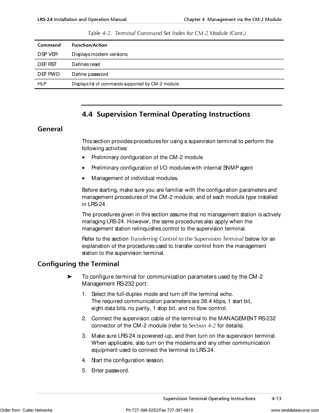
Command Function/Action
Index of Commands
Errors Execution
Supervision Terminal Operating Instructions
Terminal Command Set Index for CM-2 Module
Factory set password is radlrs
Changing the Password
To change the password Type Node 13 DEF PWD Enter
Password Menu Screen appears see Figure
To configure an SMOD-type module on the DSP HUB data form
Configuration by Snmp Network Management Stations
Node nn command Enter
To configure an IMOD-type module on the DSP HUB data form
Order to receive traps
Smod modems
Diagnostic Tests Troubleshooting
Alarms
Indicator Status
Error Messages
Message Interpretation
Error Messages
Troubleshooting and Diagnostics Error Messages
Pin Function
Table A-1. Pin Allocation for Station CLK Connector
Station Clock Interface LRSI-F-CM1 Module
Pin Function Direction
Management RS-232 Port Interface-LRSI-F-CM1 Module
Management RS-232 Port Interface-CM-1/CM-2 Modules
Cont
Station CLK Connector LRSI-F-CM2 Modules
Ethernet Interface Connector LRSI-F2-CM2 Module
Ethernet Interface Connector LRSI-F1-CM2 Module
Power Connectors
Table A-5. LRSI-F1-CM Module, Ethernet Interface Connector
LRS-PS-FEED Panels
AC-Powered Unit
Site Requirements
DC-Powered Unit
Not properly grounded
DC-powered LRS-PS-FEED units require a -48 VDC power source
Preparation for Installation
Installation and Operation
Power Connection
Rack Installation
Operation
Phantom Voltage Connection
Order from Cutter Networks Ph727-398-5252/Fax727-397-9610
Snmp Environment
Scope
Snmp Principles
Snmp Operations
MIB Structure
Management Information Base
General, Snmp agents support two types of access rights
Access Restriction Using Snmp Communities
Management Domains Under Snmp
MIBs Supported by the LRS-24 Snmp Agent
IP Environment
IP Environment
CM-2 Communities
IP Address Structure
Address Class First Byte Address Range
Table C-1. IP Address Class
Byte
Assignment of Addresses
Default Gateway
Net and Subnet Masks
Routing of IP Management Traffic
Snmp Traps
Snmp Traps
Appendix D CM-2 Management Commands
Defining Dial-Up Modem Parameters
Procedure
Purpose
Format
Table D-1. DEF Call Fields
Command Fields
Table D-1lists the fields appearing on the data form
Defining LRS-24 And CM-2 Snmp Agent Parameters
Returning to Terminal Mode
Table D-2describes fields on the data form
Table D-2. DEF HUB Command Fields
Hoursminutesseconds
Bootp ON/OFF
Table D-3 DEF HUB Command Fields
Defining Management Stations
HUB NMS Trap Update IP Addr
Download Main Menu
Defining CM-2 Download Parameters
Typical data form is shown in Figure D-4
Table D-4. Download Main Menu Options
CM2 Download via LAN
To download via LAN
Type Download via LAN screen appears
CM2 Download via CM2 Flash
CM2 Download via Xmodem
Change CM-2 Software Version
To download via Xmodem 1. Type
Type View CM2 Software Version screen appears
View CM-2 Software Version
To view CM-2 Software Version
First line describes the version that is currently running
Defining Modem Download Parameters
Controls the program version and allows six options
Node nn DEF MDL Nn is the slot number
Modem Download via Xmodem
Modem Download via LAN
Modem Download via CM2 Flash
To download Modem via LAN
To download to remote modem via Modem Flash
Download to Remote Modem via Modem Flash
Download to Remote Modem VIA MODEM’S Flash
Modem Status Master Permanent Select Modem Modem 1 Local
View Modem Version on Modem Flash
Changing Modem Version
To change the Modem Version
Type Changing Modem Version screen appears see Figure D-14
To view version of Modem software Type NODE13 DSP VER Enter
Viewing Modem Version
Modem Version screen appears see Figure D-16
Table D-5. Modem Version Parameters
Modem Reset Factory Reset Card Reset
Modem Advanced Setup
Defining I/O Module Management Parameters
Node nn DEF OPR
Defines card type, name, and connection to a remote modem
Defining Card Configuration
Define Card Type
Empty Null Linked
Node nn DEF PRM
Defining I/O Module Operational Parameters
Defining Supervision Terminal Type
Modem Setup
Data Rate
Parity CD Sense Clock Source LOC/REM Lintrrcv
Terminal selection form appears. a typical form is shown
Table D-6. Terminal Types
To select a terminal
Define Terminal Type
Node nn DEF TST
Defining I/O Module Diagnostics
Modem Diagnostic
Auto Configuration Menu
Defining Auto-Configuration
Auto-Configuration Menu screen appears see Figure D-22
To edit the Configuration
Editing the Configuration
File number
User String
You can send or execute Hub Configuration files
Hub Configuration Operations
To execute a Hub Configuration file
Operations for HUB Configuration File
Input Imedance
To configure a modem file
Editing a Modem File
To configure according to modem type
To execute the modem configuration file
Edit AUTO-CONFIGURATION
Edit Auto Configuration
AUTO-CONFIGURATION According to Modem Type
To configure according to a specific slot/modem list
Modem Number
AUTO-CONFIGURATION According to SLOT/MODEM List
To send a configuration file to the LRS-24 hub
Sending Configuration Files
To send the file by Tftp
Select Tftp Download via LAN Screen appears see Figure D-33
Viewing Configuration Files in the Hub
Creating Files from an Existing Configuration
To create a file from the existing configuration
To view configuration files in the LRS-24 hub
View Configuration Files in HUB
Displaying General Alarm Status
Alarm status display form appears. a typical form is shown
Message Description
Display Format
Table D-7. Current Management Fields
Node nn DSP ALT
Displaying I/O Module Alarm Status
Modem Alram Status
Displaying System Status
Typical display is shown in Figure D-40
Data Description
Table D-8describes the fields in the display
Table D-8. Module Status Fields
Node nn DSP LOG
Displaying Alarms Log
To display the desired log Type DSP nn DSP LOG Enter
Modem LOG File
To display the information Type DSP nn DSP STT Enter
Displaying I/O Module Status
Node nn DSP STT
Define Password
Define CM-2 Reset
To reset the CM-2 card
To define the password Type Node 13 DEF PWDEnter
To enter the help system Type HLP Enter
Displaying Command Options
Type password Select YES or no to Enable Password
Figure D-45. Hub Terminal Commands Screen
Command Description
Table D-9. Hub Terminal Commands Screen
Order from Cutter Networks Ph727-398-5252/Fax727-397-9610
Cables
Index
User modules
RADview
Index