4. Service procedures
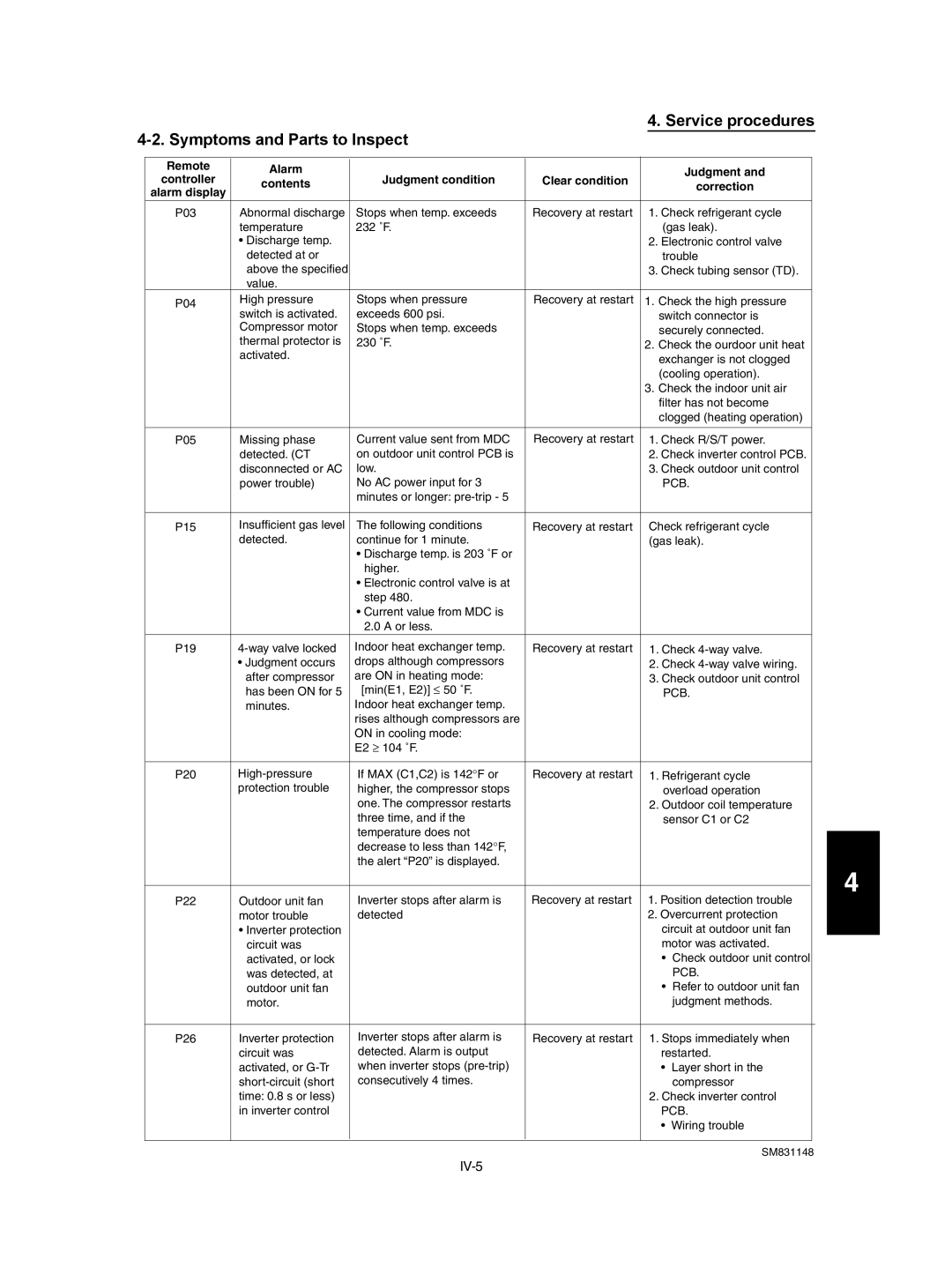
4-2. Symptoms and Parts to Inspect
Remote | Alarm | Judgment condition | Clear condition |
| Judgment and |
|
controller | contents |
| correction |
| ||
alarm display |
|
|
|
| ||
|
|
|
|
|
| |
P03 | Abnormal discharge | Stops when temp. exceeds | Recovery at restart | 1. Check refrigerant cycle |
| |
| temperature | 232 ˚F. |
| (gas leak). |
| |
| • Discharge temp. |
|
| 2. Electronic control valve |
| |
| detected at or |
|
| trouble |
| |
| above the specified |
|
| 3. Check tubing sensor (TD). |
| |
| value. |
|
|
|
|
|
P04 | High pressure | Stops when pressure | Recovery at restart | 1. Check the high pressure |
| |
| switch is activated. | exceeds 600 psi. |
| switch connector is |
| |
| Compressor motor | Stops when temp. exceeds |
| securely connected. |
| |
| thermal protector is | 230 ˚F. |
| 2. Check the ourdoor unit heat |
| |
| activated. |
|
| exchanger is not clogged |
| |
|
|
|
|
| ||
|
|
|
| (cooling operation). |
| |
|
|
|
| 3. Check the indoor unit air |
| |
|
|
|
| filter has not become |
| |
|
|
|
| clogged (heating operation) |
| |
|
|
|
|
|
| |
P05 | Missing phase | Current value sent from MDC | Recovery at restart | 1. Check R/S/T power. |
| |
| detected. (CT | on outdoor unit control PCB is |
| 2. Check inverter control PCB. |
| |
| disconnected or AC | low. |
| 3. Check outdoor unit control |
| |
| power trouble) | No AC power input for 3 |
| PCB. |
| |
|
| minutes or longer: |
|
|
|
|
|
|
|
|
|
| |
P15 | Insufficient gas level | The following conditions | Recovery at restart | Check refrigerant cycle |
| |
| detected. | continue for 1 minute. |
| (gas leak). |
| |
|
| • Discharge temp. is 203 ˚F or |
|
|
|
|
|
| higher. |
|
|
|
|
|
| • Electronic control valve is at |
|
|
|
|
|
| step 480. |
|
|
|
|
|
| • Current value from MDC is |
|
|
|
|
|
| 2.0 A or less. |
|
|
|
|
P19 | Indoor heat exchanger temp. | Recovery at restart | 1. Check |
| ||
| • Judgment occurs | drops although compressors |
| 2. Check |
| |
| after compressor | are ON in heating mode: |
| 3. Check outdoor unit control |
| |
| has been ON for 5 | [min(E1, E2)] ≤ 50 ˚F. |
| PCB. |
| |
| minutes. | Indoor heat exchanger temp. |
|
|
|
|
|
| rises although compressors are |
|
|
|
|
|
| ON in cooling mode: |
|
|
|
|
|
| E2 ≥ 104 ˚F. |
|
|
|
|
|
|
|
|
|
| |
P20 | If MAX (C1,C2) is 142°F or | Recovery at restart | 1. Refrigerant cycle |
| ||
| protection trouble | higher, the compressor stops |
| overload operation |
| |
|
| one. The compressor restarts |
| 2. Outdoor coil temperature |
| |
|
| three time, and if the |
| sensor C1 or C2 |
| |
|
| temperature does not |
|
|
|
|
|
| decrease to less than 142°F, |
|
|
|
|
|
| the alert “P20” is displayed. |
|
|
|
|
|
|
|
|
|
| |
P22 | Outdoor unit fan | Inverter stops after alarm is | Recovery at restart | 1. Position detection trouble |
| |
| motor trouble | detected |
| 2. Overcurrent protection |
| |
| • Inverter protection |
|
| circuit at outdoor unit fan |
| |
| circuit was |
|
| motor was activated. |
| |
| activated, or lock |
|
| • | Check outdoor unit control |
|
| was detected, at |
|
|
| PCB. |
|
| outdoor unit fan |
|
| • | Refer to outdoor unit fan |
|
| motor. |
|
|
| judgment methods. |
|
|
|
|
|
|
| |
P26 | Inverter protection | Inverter stops after alarm is | Recovery at restart | 1. Stops immediately when |
| |
| circuit was | detected. Alarm is output |
| restarted. |
| |
| activated, or | when inverter stops |
| • | Layer short in the |
|
| consecutively 4 times. |
|
| compressor |
| |
| time: 0.8 s or less) |
|
| 2. Check inverter control |
| |
| in inverter control |
|
| PCB. |
| |
|
|
|
| • | Wiring trouble |
|
|
|
|
|
|
|
|
|
|
|
|
|
|
|
|
|
|
|
| SM831148 | |
4 |
