4. Service procedures
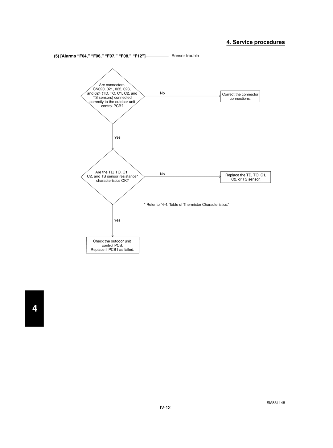
(5) [Alarms “F04,” “F06,” “F07,” “F08,” “F12”] | Sensor trouble |
Are connectors |
|
|
CN020, 021, 022, 023, | No |
|
and 024 (TD, TO, C1, C2, and | Correct the connector | |
TS sensors) connected |
| connections. |
correctly to the outdoor unit |
|
|
control PCB? |
|
|
Yes
Are the TD, TO, C1, | No | Replace the TD, TO, C1, | |
C2, and TS sensor resistance* | |||
| C2, or TS sensor. | ||
characteristics OK? |
| ||
|
|
* Refer to
Yes
Check the outdoor unit control PCB.
Replace if PCB has failed.
4 |
