4 |
|
|
|
| 4. Service procedures | |
|
|
|
|
|
|
Remote | Alarm |
|
| Judgment and correction |
|
controller | Judgment condition | Clear condition |
| ||
contents |
| ||||
alarm display |
|
|
|
|
|
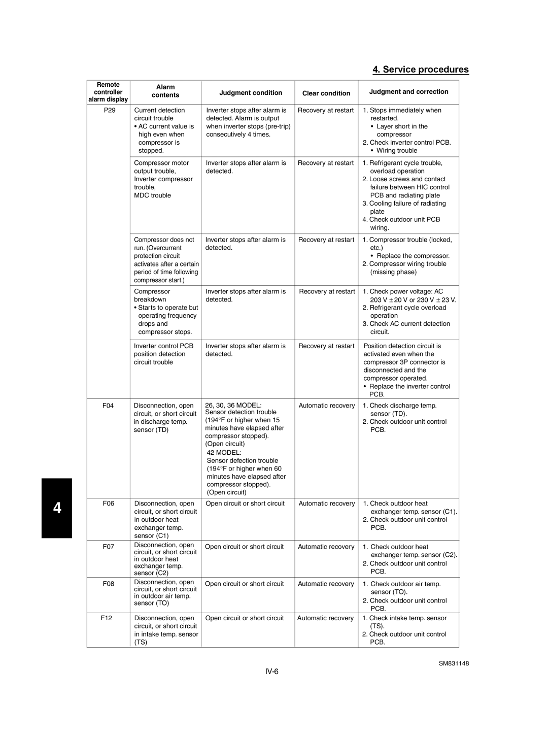
P29 | Current detection | Inverter stops after alarm is | Recovery at restart | 1. Stops immediately when |
|
| circuit trouble | detected. Alarm is output |
| restarted. |
|
| • AC current value is | when inverter stops |
| • Layer short in the |
|
| high even when | consecutively 4 times. |
| compressor |
|
| compressor is |
|
| 2. Check inverter control PCB. |
|
| stopped. |
|
| • Wiring trouble |
|
|
|
|
|
|
|
| Compressor motor | Inverter stops after alarm is | Recovery at restart | 1. Refrigerant cycle trouble, |
|
| output trouble, | detected. |
| overload operation |
|
| Inverter compressor |
|
| 2. Loose screws and contact |
|
| trouble, |
|
| failure between HIC control |
|
| MDC trouble |
|
| PCB and radiating plate |
|
|
|
|
| 3. Cooling failure of radiating |
|
|
|
|
| plate |
|
|
|
|
| 4. Check outdoor unit PCB |
|
|
|
|
| wiring. |
|
|
|
|
|
|
|
| Compressor does not | Inverter stops after alarm is | Recovery at restart | 1. Compressor trouble (locked, |
|
| run. (Overcurrent | detected. |
| etc.) |
|
| protection circuit |
|
| • Replace the compressor. |
|
| activates after a certain |
|
| 2. Compressor wiring trouble |
|
| period of time following |
|
| (missing phase) |
|
| compressor start.) |
|
|
|
|
|
|
|
|
|
|
| Compressor | Inverter stops after alarm is | Recovery at restart | 1. Check power voltage: AC |
|
| breakdown | detected. |
| 203 V ± 20 V or 230 V ± 23 V. |
|
| • Starts to operate but |
|
| 2. Refrigerant cycle overload |
|
| operating frequency |
|
| operation |
|
| drops and |
|
| 3. Check AC current detection |
|
| compressor stops. |
|
| circuit. |
|
|
|
|
|
|
|
| Inverter control PCB | Inverter stops after alarm is | Recovery at restart | Position detection circuit is |
|
| position detection | detected. |
| activated even when the |
|
| circuit trouble |
|
| compressor 3P connector is |
|
|
|
|
| disconnected and the |
|
|
|
|
| compressor operated. |
|
|
|
|
| • Replace the inverter control |
|
|
|
|
| PCB. |
|
F04 | Disconnection, open | 26, 30, 36 MODEL: | Automatic recovery | 1. Check discharge temp. |
|
| circuit, or short circuit | Sensor detection trouble |
| sensor (TD). |
|
| in discharge temp. | (194°F or higher when 15 |
| 2. Check outdoor unit control |
|
| sensor (TD) | minutes have elapsed after |
| PCB. |
|
|
| compressor stopped). |
|
|
|
|
| (Open circuit) |
|
|
|
|
| 42 MODEL: |
|
|
|
|
| Sensor defection trouble |
|
|
|
|
| (194°F or higher when 60 |
|
|
|
|
| minutes have elapsed after |
|
|
|
|
| compressor stopped). |
|
|
|
|
| (Open circuit) |
|
|
|
|
|
|
|
|
|
F06 | Disconnection, open | Open circuit or short circuit | Automatic recovery | 1. Check outdoor heat |
|
| circuit, or short circuit |
|
| exchanger temp. sensor (C1). |
|
| in outdoor heat |
|
| 2. Check outdoor unit control |
|
| exchanger temp. |
|
| PCB. |
|
| sensor (C1) |
|
|
|
|
F07 | Disconnection, open | Open circuit or short circuit | Automatic recovery | 1. Check outdoor heat |
|
| circuit, or short circuit |
|
| exchanger temp. sensor (C2). |
|
| in outdoor heat |
|
|
| |
|
|
| 2. Check outdoor unit control |
| |
| exchanger temp. |
|
|
| |
|
|
| PCB. |
| |
| sensor (C2) |
|
|
| |
F08 | Disconnection, open | Open circuit or short circuit | Automatic recovery | 1. Check outdoor air temp. |
|
| circuit, or short circuit |
|
| sensor (TO). |
|
| in outdoor air temp. |
|
|
| |
|
|
| 2. Check outdoor unit control |
| |
| sensor (TO) |
|
|
| |
|
|
| PCB. |
| |
|
|
|
|
| |
F12 | Disconnection, open | Open circuit or short circuit | Automatic recovery | 1. Check intake temp. sensor |
|
| circuit, or short circuit |
|
| (TS). |
|
| in intake temp. sensor |
|
| 2. Check outdoor unit control |
|
| (TS) |
|
| PCB. |
|
|
|
|
| SM831148 | |
