|
|
|
|
|
|
|
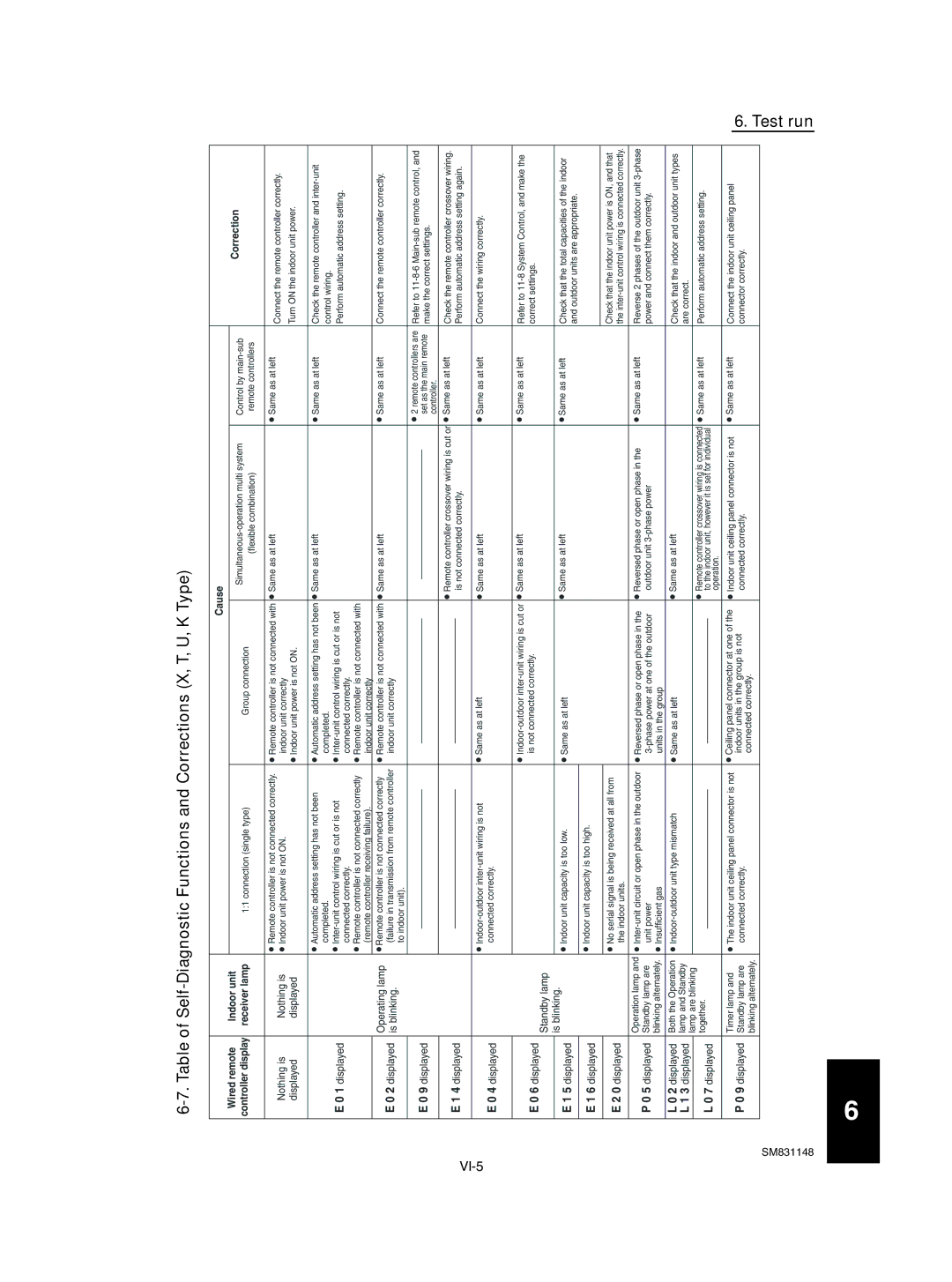
| Cause |
|
| |||
| Wired remote | Indoor unit |
|
|
|
|
|
|
|
|
|
| Correction |
|
|
|
|
|
| Control by | |||||||
| controller display | receiver lamp |
| 1:1 connection (single type) |
| Group connection |
| ||||||
|
|
|
| (flexible combination) | remote controllers |
| |||||||
|
|
|
|
|
|
|
|
|
|
| |||
|
|
|
|
|
|
|
|
|
|
|
|
|
|
| Nothing is | Nothing is | ● Remote controller is not connected correctly. | ● Remote controller is not connected with | ● Same as at left | ● Same as at left | Connect the remote controller correctly. | ||||||
| ● Indoor unit power is not ON. | indoor unit correctly |
|
|
|
| |||||||
|
|
|
|
| Turn ON the indoor unit power. | ||||||||
| displayed | displayed |
|
|
| ● Indoor unit power is not ON. |
|
|
|
| |||
|
|
|
|
|
|
|
|
|
|
|
|
|
|
|
|
| ● Automatic address setting has not been | ● Automatic address setting has not been | ● Same as at left | ● Same as at left | Check the remote controller and | ||||||
|
|
| completed. | completed. |
|
|
|
| control wiring. | ||||
| E 0 1 displayed |
| ● | ● |
|
|
|
| Perform automatic address setting. | ||||
|
|
| connected correctly. | connected correctly. |
|
|
|
|
| ||||
|
|
| ● Remote controller is not connected correctly | ● Remote controller is not connected with |
|
|
|
|
| ||||
|
|
| (remote controller receiving failure). | indoor unit correctly |
|
|
|
|
| ||||
| E 0 2 displayed | Operating lamp | ● Remote controller is not connected correctly | ● Remote controller is not connected with | ● Same as at left | ● Same as at left | Connect the remote controller correctly. | ||||||
| is blinking. | (failure in transmission from remote controller | indoor unit correctly |
|
|
|
|
| |||||
|
|
| to indoor unit). |
|
|
|
|
|
|
|
| ||
| E 0 9 displayed |
|
|
|
|
|
|
|
|
|
| ● 2 remote controllers are | Refer to |
|
|
|
|
|
|
|
|
|
|
| set as the main remote | make the correct settings. | |
|
|
|
|
|
|
|
|
|
|
| |||
|
|
|
|
|
|
|
|
|
|
|
| controller. |
|
| E 1 4 displayed |
|
|
|
|
|
|
| ● Remote controller crossover wiring is cut or | ● Same as at left | Check the remote controller crossover wiring. | ||
|
|
|
|
|
|
|
| is not connected correctly. |
| Perform automatic address setting again. | |||
|
|
|
|
|
|
|
| ||||||
|
|
|
|
|
|
|
|
|
|
|
|
| |
E 0 4 displayed |
| ● | ● Same as at left | ● Same as at left | ● Same as at left | Connect the wiring correctly. | |||||||
|
| connected correctly. |
|
|
|
|
|
|
|
| |||
|
|
|
|
|
|
|
|
|
|
|
|
|
|
|
|
|
|
|
| ● | ● Same as at left | ● Same as at left | Refer to | ||||
| E 0 6 displayed | Standby lamp |
|
|
| is not connected correctly. |
|
|
|
| correct settings. | ||
|
|
|
|
|
|
|
|
|
|
|
|
| |
|
| is blinking. |
|
|
|
|
|
|
|
|
|
|
|
| E 1 5 displayed | ● Indoor unit capacity is too low. | ● Same as at left | ● Same as at left | ● Same as at left | Check that the total capacities of the indoor | |||||||
|
| ||||||||||||
|
|
|
|
|
|
|
|
|
|
|
|
| and outdoor units are appropriate. |
| E 1 6 displayed |
| ● Indoor unit capacity is too high. |
|
|
|
|
|
|
|
| ||
|
|
|
|
|
|
|
|
|
|
|
|
| |
|
|
|
|
|
|
|
|
|
|
|
|
|
|
|
|
|
|
|
|
|
|
|
|
|
|
| Check that the indoor unit power is ON, and that |
| E 2 0 displayed |
| ● No serial signal is being received at all from |
|
|
|
|
|
|
| |||
|
| the indoor units. |
|
|
|
|
|
|
| the | |||
|
|
|
|
|
|
|
|
|
|
|
|
|
|
| P 0 5 displayed | Operation lamp and | ● | ● Reversed phase or open phase in the | ● Reversed phase or open phase in the | ● Same as at left | Reverse 2 phases of the outdoor unit | ||||||
| Standby lamp are | unit power | outdoor unit |
| power and connect them correctly. | ||||||||
|
| blinking alternately. | ● Insufficient gas | units in the group |
|
|
|
|
| ||||
| L 0 2 displayed | Both the Operation | ● | ● Same as at left | ● Same as at left |
| Check that the indoor and outdoor unit types | ||||||
| L 1 3 displayed | lamp and Standby |
|
|
|
|
|
|
|
|
|
| are correct. |
|
| lamp are blinking |
|
|
|
|
|
|
|
|
|
|
|
|
|
|
|
|
|
|
| ● Remote controller crossover wiring is connected | ● Same as at left | Perform automatic address setting. | |||
| L 0 7 displayed | together. |
|
|
|
|
|
| |||||
|
|
|
|
|
|
|
| to the indoor unit, however it is set for individual |
|
| |||
|
|
|
|
|
|
|
|
|
| ||||
|
|
|
|
|
|
|
|
| operation. |
|
| ||
| P 0 9 displayed | Timer lamp and | ● The indoor unit ceiling panel connector is not | ● Ceiling panel connector at one of the | ● Indoor unit ceiling panel connector is not | ● Same as at left | Connect the indoor unit ceiling panel | ||||||
| Standby lamp are | connected correctly. | indoor units in the group is not | connected correctly. |
| connector correctly. | |||||||
|
| blinking alternately. |
|
|
| connected correctly. |
|
|
|
|
| ||
|
|
|
|
|
|
|
|
|
|
|
|
| |
|
|
|
|
|
|
|
|
|
|
|
|
|
|
SM831148 |
|
|
|
|
|
|
|
|
|
|
|
| |
6. Test run
6