JW-21MN
JW-21MN
Installation
Safety Precautions
Wiring Compel
Maintenance Prohibit
Use
ME-NET Module JW-21MN
Table of contents
Errors and Countermeasures 12-1 to
Setting of Switches and Parameter 11-1 to
Description for Computer Link Operation 10-1 to
13-1
Support Tools 14-1 to Specifications 15-1 to
Appendix 16-1 to
Data link function
Features and Functions
Computer link function
Installation
Wiring
Connector
Maintenance
Treatment
Static electricity
Allocation of relay number
System Configuration
JW20H JW-21MN JW-21MN JW30H
Name and Function of Each Part
Front view
Installation procedure
Installation
Remarks
Processing of Cables
Name Model Maker
Processing cable end
Cutting of coating, external conductor, and insulator
Fine adjustment of blade cutting depth
Removal of coating, external conductor, and insulator
Display of blade setting
Processing of cable end
Connector crimping procedure
Connector ME-GP-01 Processing procedure Insert a sleeve
Required tools Hand-held crimping tool
Crimping contact
Insulation test
Fixing the connector
Conductivity test
Cable trunk and branch lines
Wiring Method
Relaying of trunk cables
Cable wiring procedure in control panel
Page
Waterproof and insulation processing of connectors
Branch connector
Straight connector
Remarks
Wiring of cables at outside control panels
Check after wiring
Branching method
Station number of the additional station
Reason
Memory address for data links
Memory Address on the ME-NET
Memory address map against JW20/JW20H
Memory address map against JW30H
JW30H address ME-NET address
Memory addresses for computer links
JW20/20H ME-NET address Capacity
JW30H address ME-NET address Capacity Remarks
Description for Data Link Operation
Communication method
Data link Standard function
Relay link
Data link Save memory function
Setting item Set location
Register link
Required transmission time and communication delay time
Required transmission time
Communication delay time
Data transmission between master PC and slave PC
An example of synchronized transfer by OUT instruction
Expansion of network
Multiple installation of the JW-21MN
Case of mounting 4 sets of JW-21MN
Hierarchical link
Basic commands
Optional commands
Description for Computer Link Operation
Computer link function
Basic commands
10-2
10-3
Optional commands
Communication format, basic pattern
Write mode assignment None Communication format
Read free memory size
Monitor TMR, CNT, and MD
10-4
Setting PC mode
Reading PC mode
10-5
Writing system memory
Reading system memory
10-6
Setting date
Write mode assignment 1 or Communication format
Reading date
10-7
Reading time
Setting time
10-8
Monitor step status JW20/JW20H only
Correct clock time
10-9
Write mode assignment
Read the optional parameters
Set the optional parameters
10-10
Set the special I/O parameters
Read the special I/O parameters
10-11
Set the secret function JW30H only
Release the secret function, register password JW30H only
10-12
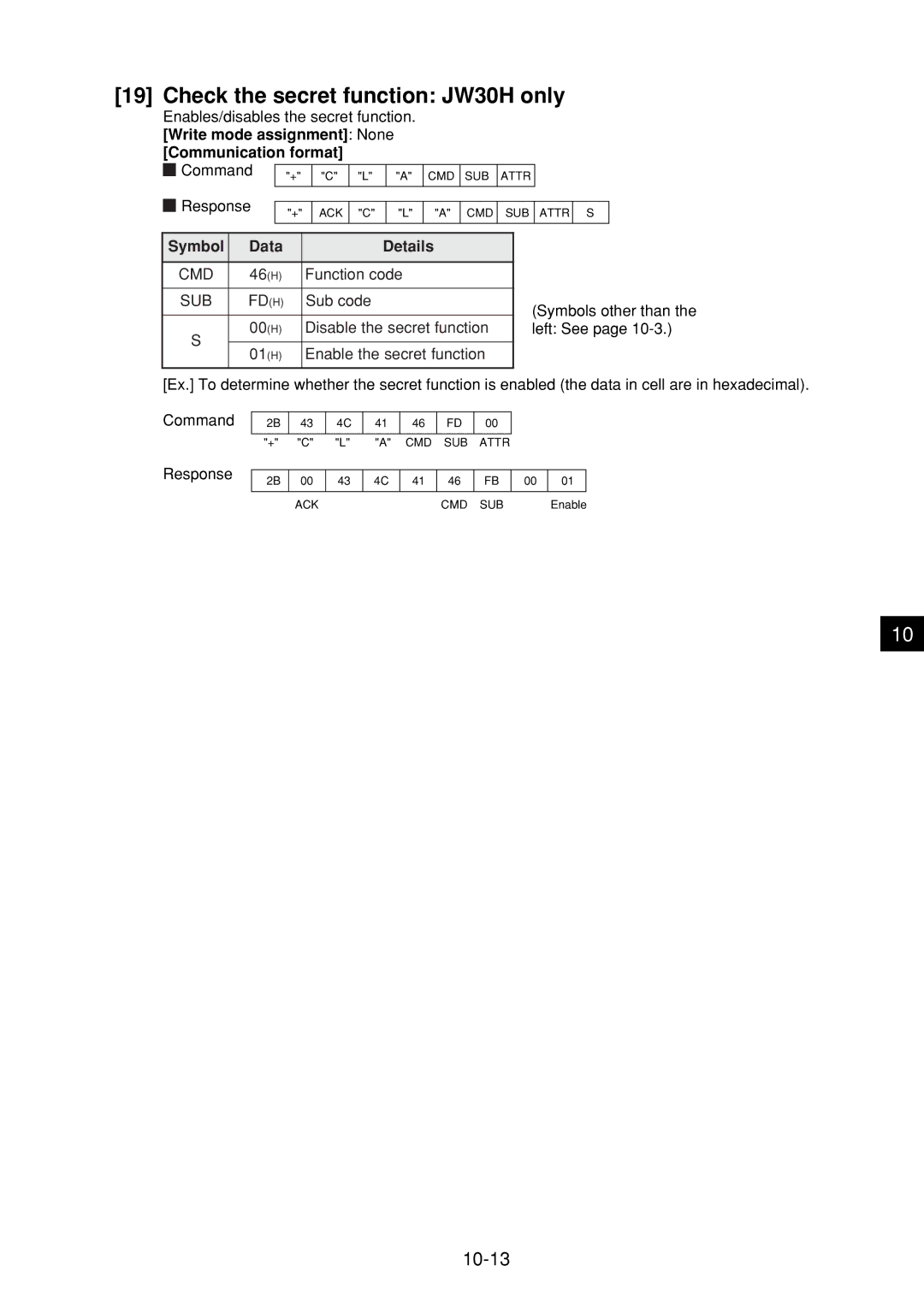
Check the secret function JW30H only
10-13
Response on error
10-14
Operation procedure
Setting of Switches and Parameter
11-1
Switch setting of master station and slave station
Mode switch Mode
Module No. switch Unit no
11-2
Station number switch STA no
Termination resistance switch LT
11-3
Reference Need for the termination resistance
Shield ground switch LG
11-4
Setting contents of master station parameters
11-6
Value H
Parameter for setting in master station
Parameter for setting in slave station
Communication area map
11-7
11-8
+ h
11-9
11-10
Example for setting
Maser station Slave station Standard Save memory
When master station PC is JW20/JW20H
11-11
When master station PC is JW30H
11-12
Setting procedure
11-13
Example Stop operation of data link HEX hexadecimal, byte
11-14
Stop operation of data link HEX hexadecimal, byte
Set number of connecting stations DCM decimal, byte
Data link function setting HEX hexadecimal, byte
11-15
11-16
Set top address of register link area on the master station
11-17
Set in parameter addresses 005000 to
11-18
11-19
Set connection status of slave station Bit pattern, byte
11-20
11-21
PC operation
Contents
Setting item
11-22
Setting range of flag area
When PC is JW20/JW20H
When PC is JW30H
11-23
11-24
Turn on the power of slave station PC Connect support tools
11-25
11-26
11-27
11-28
Errors and Countermeasures
Indication lamps
12-1
Details Measure
Flag
Remark
Case of a master station
12-3
Communication monitor flag
Operation condition monitor flag
Case of slave station 01 to
12-4
Monitor operation condition by each station PC
12-5
Storage of error code
12-6
System memory #170 to 177 option module error code
System memory #160 to 167 self diagnosis error code
System memory #150 monitor error switch number
12-7
Error history
12-8
Replacement of the JW-21MN
13-1
Record and load by ladder software JW-92SP, JW-50SP Record
Support Tools
14-1
Load
14-2
Load to the personal computer
Stop operation of the JW-21MN
Specifications
General specifications
Communication specifications
Specification
Data link specifications
Standard function Specifications
Save memory function Specifications
15-2
Outside dimensional drawings
Computer link specifications
15-3
Appendix
Maintenance and check
16-1
Check flow chart
Recovery method at communication errors
16-2
Check cable/connector
16-3
16-4
Cause Countermeasure
16-5
007764 to
Switches required check in the JW-21MN
Check items of cables and connectors
16-6
Other cases
Check the errors timing
Identify the error station
When identification of the cause is difficult
16-7
16-8
Table of parameter memory
Master station
Set contents Setting method value, example
16-9
16-10
16-11
16-12
Slave station 01 to
Special functions unique to the JW-21MN
16-13
Remote programming and remote monitor
Support tool Opposite module Connection module
16-14
Function Standard network connection
Expansion network connection
Operation example
Network setting
16-15
When used with a computer link
Parameter setting by remote function
16-16
Alphabetical Index
Operation procedure
Waterproof and insulation processing of connectors