Model 9200 Programmable Dual-loop Controller
•The “Chart” button will switch the display to the video recorder display. Use of the “Chart” display is explained below.
•The “Alarm Ack” button is used to acknowledge an alarm. The alarm is displayed in the lower left hand corner of the status screen. A red “ALM” block in the top right corner of the screen displays an alarm condition. The alarm will either be a flashing number, which indicates a program operator alarm, or a flashing message, which indicates a program system alarm.
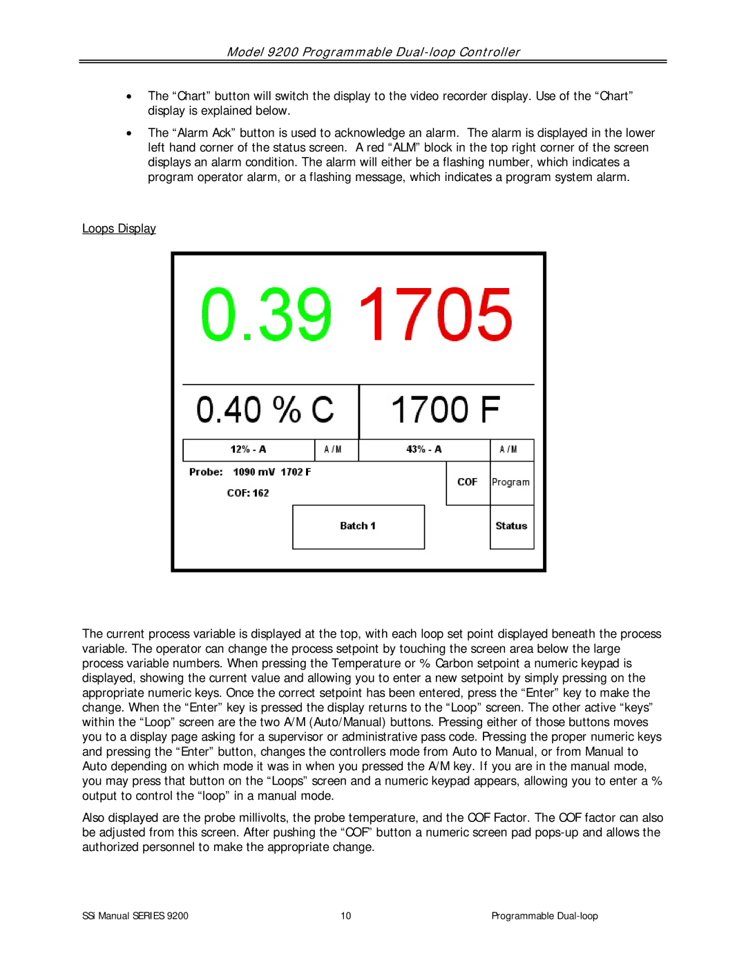
Loops Display
The current process variable is displayed at the top, with each loop set point displayed beneath the process variable. The operator can change the process setpoint by touching the screen area below the large process variable numbers. When pressing the Temperature or % Carbon setpoint a numeric keypad is displayed, showing the current value and allowing you to enter a new setpoint by simply pressing on the appropriate numeric keys. Once the correct setpoint has been entered, press the “Enter” key to make the change. When the “Enter” key is pressed the display returns to the “Loop” screen. The other active “keys” within the “Loop” screen are the two A/M (Auto/Manual) buttons. Pressing either of those buttons moves you to a display page asking for a supervisor or administrative pass code. Pressing the proper numeric keys and pressing the “Enter” button, changes the controllers mode from Auto to Manual, or from Manual to Auto depending on which mode it was in when you pressed the A/M key. If you are in the manual mode, you may press that button on the “Loops” screen and a numeric keypad appears, allowing you to enter a % output to control the “loop” in a manual mode.
Also displayed are the probe millivolts, the probe temperature, and the COF Factor. The COF factor can also be adjusted from this screen. After pushing the “COF” button a numeric screen pad
SSi Manual SERIES 9200 | 10 | Programmable |