Heat Pump Type
Indoor Unit
Outdoor Unit
High Wall, Heat Pump Type
WIRING DIAGRAM
Cord Heater Installation Work
SAFETY PRECAUTIONS
SPECIFICATIONS
TO DISCONNECT THE APPLIANCE FROM THE MAIN POWER SUPPLY
1. SAFETY PRECAUTIONS
DANGER
New Refrigerant Air Conditioner Installation
For Reference
2-1. Specifications
2. SPECIFICATIONS
Heating
2-2. Operation Characteristic Curve
2-3. Capacity Variation Ratio According to Temperature
Cooling
3-2-1. Piping Materials and Joints Used
3-1. Safety During Installation/Servicing
3-2. Refrigerant Piping Installation
3. REFRIGERANT R410A
2. Joints
1. Flare processing procedures and precautions
3-2-2. Processing of Piping Materials
Fig. 3-2-1 Flare processing dimensions
2. Flare Connecting Procedures and Precautions
3-3-1. Required Tools
3-3. Tools
Fig. 3-4-1 Configuration of refrigerant charging
3-4. Recharging of Refrigerant
3-5-1. Materials for Brazing
3-5. Brazing of Pipes
3. Low temperature brazing filler
1. Reason why flux is necessary
3. Types of flux
2. Characteristics required for flux
3-5-3. Brazing
Never use gas other than Nitrogen gas
RAS-B10GKVP-E RAS-B13GKVP-E RAS-B16GKVP-E
4. CONSTRUCTION VIEWS
4-1. Indoor Unit
Detailed B leg part
4-2. Outdoor Unit
RAS-10GAVP-E, RAS-13GAVP-E, RAS-16GAVP-E
Detailed A leg part
RAS-10GAVP-E, RAS-13GAVP-E, RAS-16GAVP-E
5. WIRING DIAGRAM
5-1. Outdoor Unit
5-2. Indoor Unit
Specifications
6. SPECIFICATIONS OF ELECTRICAL PARTS
6-1. Indoor Unit
6-2. Outdoor Unit
RAS-B10GKVP-E/RAS-10GAVP-E
7. REFRIGERANT CYCLE DIAGRAM
7-1. Refrigerant Cycle Diagram
10mdifference
RAS-B13GKVP-E/RAS-13GAVP-E, RAS-B16GKVP-E/RAS-16GAVP-E
heightAllowable
Heating
2. Connecting piping condition 7.5 m
7-2. Operation Data Cooling
RAS-B10GKVP-E, RAS-B13GKVP-E, RAS-B16GKVP-E
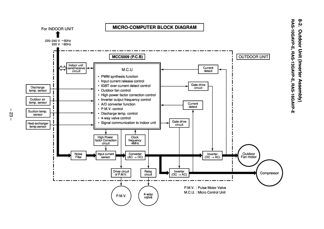
8. CONTROL BLOCK DIAGRAM
8-1. Indoor Unit
REMOTE CONTROLLER
10GAVP-E, RAS-13GAVP
MICRO-COMPUTER BLOCK DIAGRAM
Assembly
Outdoor Unit Inverter
2. Role of outdoor unit controller
9. OPERATION DESCRIPTION
9-1. Outline of Air Conditioner Control
1. Role of indoor unit controller
Hi-POWER button on the remote controller is pressed
FILTER Indicator
Remote Controller and Its Fuctions
Hi-POWER Mode
Operation flow and applicable data, etc
Remote controller
Indoor unit
Outdoor unit
3. AUTO operation
Operation flow and applicable data, etc
Description
1. Basic 2. Cooling/Heating operation
Fan speed
Indication
Indication
Operation flow and applicable data, etc
Description
In heating operation
3. Outdoor fan
Indoor unit
Remote controller
Operation flow and applicable data, etc
Description
In heating operation
Operation flow and applicable data, etc
Description
In cooling/dry operation
Condition
Operation flow and applicable data, etc
In case of operation stop
Description
1 Louver position in cooling operation
Powerful
Operation flow and applicable data, etc
Description
Cooling operation
Operation flow and applicable data, etc
Description
Cooling operation
Present status
Operation flow and applicable data, etc
Description
Operation button
2. Description
Operation flow and applicable data, etc
Description
1. Purpose
Stop by
Move to
SH control
PMV open degree control
1. Purpose
Clean operation
Operation flow and applicable data, etc
Description
Description
16. Clean operation Setting the clean operation release release
Setting the clean operation
Operation flow and applicable data, etc
Description
Setting the remote controller
Setting the selector switch on the main unit
Operation flow and applicable data, etc
9-3. Auto Restart Function
9-3-1. How to Set the Auto Restart Function
When the unit is standby Not operating
When the unit is in operation
9-4-1. How to Turn Off FILTER Indicator
9-4. FILTER Indicator
9-3-2. How to Cancel the Auto Restart Function
9-3-3. Power Failure During Timer Operation
9-5-1. Parts Name of Remote Controller
9-5. Remote Controller and Its Fuctions
purposes of explanation
9-5-2. Name and Functions of Indications on Remote Controller
Display
In the illustration, all indications are shown for
1. Automatic operation
9-6. Hi-POWER Mode
Hi-POWER button on the remote controller is pressed
4. The Hi-POWER mode can not be set in Dry operation
10-1. Safety Cautions
10. INSTALLATION PROCEDURE
Attachment bolt arrangement of outdoor unit
10-2. Optional Parts, Accessories and Tools
10-2-1. Optional Installation Parts
10-2-2. Accessory and Installation Parts
New tools for R410A
10-2-3. Installation/Servicing Tools
Changes in the product and components
Mounting the installation plate
10-3. Indoor Unit
10-3-1. Installation Place
Remote controller
10-3-3. Electrical Work
When the installation plate is directly mounted on the wall
10-3-4. Wiring Connection How to connect the connecting cable
Piping and drain hose forming
10-3-5. Piping and Drain Hose Installation
How to remove the drain cap
How to remove the drain hose
In case of bottom right or bottom left piping
How to attach the drain cap
How to attach the drain hose
To connect the pipe after installation of the unit figure
10-3-7. Drainage
10-3-6. Indoor Unit Installation
Precautions for adding refrigerant
10-4. Outdoor Unit
10-4-1. Installation Place
Flaring size B Unit mm
10-4-2. Draining the Water
10-4-3. Refrigerant Piping Connection Flaring
Projection margin in flaring A Unit mm
IMPORTANT POINTS FOR PIPING WORK
Tightening Connection
Use a vacuum pump
Stripping length of connecting cable
Packed Valve handling precautions
10-4-5. Wiring Connection
Remote controller selector switch
10-5. Test Operation
Information
10-5-4. Remote Controller Selector Switch Setting
K The control circuitry has an uninsulated construction
11. HOW TO DIAGNOSE THE TROUBLE
K Precautions when handling the new inverter 3DV Inverter
CAUTION HIGH VOLTAGEN
Discharging method
K Precautions when inspecting the control section of the outdoor unit
11-1-3. Operation Which is not a Trouble Program Operation
11-1. First Confirmation
11-1-1. Confirmation of Power Supply
11-1-2. Confirmation of Power Voltage
11-3. Judgment by Flashing LED of Indoor Unit
11-2. Primary Judgment
11-4-1. How to Use Remote Controller in Service Mode
11-4. Self-Diagnosis by Remote Controller Check Code
Block
11-4-2. Caution at Servicing
Block distinction
Judgment and action
Judgment and action
4-way valve inverse error
Block distinction
Operation of diagnosis function
Primary check
11-5. Judgment of Trouble by Every Symptom
11-5-1. Indoor Unit Including Remote Controller
1 Power is not turned on Does not operate entirely
3 Only the indoor motor fan does not operate Primary check
Cause
Inspection procedure
5 Troubleshooting for remote controller Primary check
2 Outdoor unit stops in a little while after operation started
11-5-2. Wiring Failure Interconnecting and Serial Signal Wire
Check procedure Select phenomena described below
1 Outdoor unit does not operate
Check procedure
11-6. Check Code 1C Miswiring in indoor/outdoor units and 1E
Operation check
11-7. Troubleshooting
11-7-1. How to Check Whether the Air Purifier is Good or Not
Operation check
11-7-2. How to Check Whether the Minus Ion Generator is Good or Not
How to check output of minus ion Caution on High Voltage
Primary check
Contents
11-8. How to Diagnose Trouble in Outdoor Unit
11-8-1. Summarized Inner Diagnosis of Inverter Assembly
Diagnosis/Process flowchart
2 Inspection procedures
11-9. How to Check Simply the Main Parts
11-9-1. How to Check the P.C. Board Indoor Unit
1 Operating precautions
Causes
3 Check procedures
Procedure
Check points
11-9-2. P.C.BoardLayout
1 Sensor characteristic table
Part name
Checking procedure
11-9-3. Indoor Unit Other Parts
11-9-4. OutdoorUnit
11-9-5. Checking Method for Each Part
+ ~ ~
2. Cause
11-10. How to Simply Judge Whether Outdoor Fan Motor is Good or Bad
1. Symptom
3. How to simply judge whether outdoor fan motor is good or bad
Indoor Unit
12. HOW TO REPLACE THE MAIN PARTS
12-1
5 Remove the front panel fixing screws. 2 pcs
Page
Page
Page
Page
Pull out here
Secure using the fixing screw Screw Motor band Right Screw
Fan motor leads
Otherwise, water leak is caused
P.C. board layout
12-2. Microcomputer
12-3. Outdoor Unit
Page
Requirement
CN600
P.C. board base
CN603
CN601
Propeller fan
Detail A
Detail B
Detail C
Remarks
Procedure
Part name
Page
11 TE sensor outdoor heat exchanging temperature sensor
Cutting here
Soldered part
MCC-5009
Indoor Unit
13. EXPLODED VIEWS AND PARTS LIST
13-1
403 404 406 410401 405
Indoor Unit
407, 408
34 13, 16, 19, 22
13-2. Outdoor Unit
14, 15, 17, 18
21, 23, 24, 25
Description
Part
Description
Part
Part
13-3. P.C. Board Layout
Part
Description
Specifications/Vendor
Cord Heater Installation Work
1. Required parts for installation work Recommendation
Appendix
Appendix
2. Required tools for installation work
Specifications/Vendor
Specifications
Appendix-3
3. Cord heater installation wiring diagram
Appendix
Appendix
4. Cord heater installation work procedure
Photo / Explanatory diagram
Procedure
Appendix-5
Photo / Explanatory diagram
Procedure
Appendix
Appendix-6
Photo / Explanatory diagram
Procedure
Appendix
Appendix-7
Photo / Explanatory diagram
Procedure
Appendix
Appendix
Photo / Explanatory diagram
Procedure
Assembly
Appendix-9
5. Drawing of thermostat fixing plate
Appendix
Material SGCC-Z08, Thickness 0.8t
Appendix-10
Appendix
2 CHOME 12-32, KONAN, MINATOKU, TOKYO, 108-0075, JAPAN
TOSHIBA CARRIER CORPORATION