Split Type
Contents
New Refrigerant Air Conditioner Installation
Safety Precautions
For general public use
For Reference
Specifications
Specifications
Cooling Heating
Operation Characteristic Curve
Capacity Variation Ratio According to Temperature
Cooling
Refrigerant R410A
Safety During Installation/Servicing
Refrigerant Piping Installation
Piping Materials and Joints Used
Joints
Flare processing procedures and precautions
Processing of Piping Materials
1 Thicknesses of annealed copper pipes Thickness mm
Flare tool for R22 Conventional flare tool
Flare tool for R410A Conventional flare tool
Clutch type Wing nut type
13.2 13.5 12.70 16.6 16.0 12.9 15.88 19.7 19.0
Nm kgfcm
Flare Connecting Procedures and Precautions
43˚
Wrenches available on the market
Required Tools
Tools
General tools Conventional tools can be used
1 Configuration of refrigerant charging
Recharging of Refrigerant
Materials for Brazing
Brazing of Pipes
Flux
Brazing
Never use gas other than Nitrogen gas
Construction Views
Indoor Unit
Detailed a leg part
Outdoor Unit
Detailed B leg part
Color
Wiring Diagram
Identification
Parts name Type Specifications
Specifications of Electrical Parts
Parts name Model name Rating
Refrigerant Cycle Diagram
Refrigerant Cycle Diagram
RAS-B13GKVP-E/RAS-13GAVP-E, RAS-B16GKVP-E/RAS-16GAVP-E
Outdoor
Temperature Standard Heat exchanger Compressor Condition C
Operation Data Cooling
Outdoor MPa T1 C T2 C Rps
Operation START/STOP Operation Mode Selection
Control Block Diagram
Remote Controller
Hi-POWER Air Purifier
For Indoor Unit
Assembly
Outdoor Unit Inverter
MCC5009 P.C.B
Role of indoor unit controller
Operation Description
Outline of Air Conditioner Control
Role of outdoor unit controller
Operation Description
Filter Indicator
Remote Controller and Its Fuctions
Auto Restart Function
Indoor unit
Remote controller
Outdoor unit
+1.0
Cooling operation
Ts +
+0.5
+ M
Symbols
Indication Fan speed
+ H
Indication Fan speed
Operation flow and applicable data, etc Description
Heating operation
Cold draft preventive control
Outdoor unit
Operation command Outdoor fan control
Air conditioner Alarm
OFF status
Remote controller Indoor unit
Outdoor temp Cooling current Heating current Release value
When temperature of the indoor
Condition
Operation flow and applicable data, etc
Case of operation stop
Defrost operation
Louver position in cooling operation
Powerful
This function controls the air direction of the indoor unit
Air direction
Cooling operation
Fan
Present status Pure button Air conditioner
Operation button
Louver*1 Fan speed *2
Operation
Purpose
Td value Control operation
PMV open degree control Stop by Room temp. sensor
Move to
SH control
Ta sensor control
Clean operation
Operation mode Operation time Clean operation time
Setting the clean operation
Indoor P.C. board
Setting the remote controller
Setting the selector switch on the main unit
When the unit is standby Not operating
How to Set the Auto Restart Function
When the unit is in operation
When the system is on stand-by not operating
Power Failure During Timer Operation
How to Turn Off Filter Indicator
When the system is operating
Parts Name of Remote Controller
Display
Cooling operation
Hi-POWER mode can not be set in Dry operation
Automatic operation
Heating operation
Installation Procedure
Safety Cautions
Accessory and Installation Parts
Optional Parts, Accessories and Tools
Optional Installation Parts
Attachment bolt arrangement of outdoor unit
New tools for R410A
Installation/Servicing Tools
Changes in the product and components
New tools for R410A Applicable to R22 model Changes
Mounting the installation plate
Installation Place
Remote controller
When install the refrigerant pipes from the rear
Wiring Connection How to connect the connecting cable
When the installation plate is directly mounted on the wall
Electrical Work
Die-cutting front panel slit
How to remove the drain cap
How to remove the drain hose
Changing drain hose
Case of bottom right or bottom left piping
How to attach the drain cap
How to attach the drain hose
Left-hand connection with piping
Indoor Unit Installation
Drainage
Precautions for adding refrigerant
Projection margin in flaring a Unit mm
Draining the Water
Refrigerant Piping Connection Flaring
Flaring size B Unit mm
Tightening Connection
Use a vacuum pump
Stripping length of connecting cable
Packed Valve handling precautions
Wiring Connection
Hexagonal wrench is required
Test Operation
Auto Restart Setting
How to Set the Auto Restart
Gas Leak Test
Control circuitry has an uninsulated construction
HOW to Diagnose the Trouble
Precautions when handling the new inverter 3DV Inverter
JAVP-E series insulated type
Do not lay the circuit board assembly flat
Discharging method
First Confirmation
Confirmation of Power Supply
Confirmation of Power Voltage
Operation Which is not a Trouble Program Operation
Block display Description for self-diagnosis Code
Primary Judgment
Judgment by Flashing LED of Indoor Unit
Check
Press START/STOP button to release the service mode
Self-Diagnosis by Remote Controller Check Code
How to Use Remote Controller in Service Mode
Press on or OFF button
Remarks
Block distinction
Air Judgment and action Block Cause of operation
Status
Block distinction Operation of diagnosis function
Indoor Unit Including Remote Controller
Judgment of Trouble by Every Symptom
Is the fuse F01 blown?
Only the indoor motor fan does not operate Primary check
Is it possible to
Inspection procedure
Troubleshooting for remote controller Primary check
Outdoor unit does not operate
Wiring Failure Interconnecting and Serial Signal Wire
Inverter Assembly check
Normal time
Check procedure
Check Code 1C Miswiring in indoor/outdoor units and 1E
1C1E
Conduction check of micro-switch
Troubleshooting
How to Check Whether the Air Purifier is Good or Not
Operation check
How to Check Whether the Minus Ion Generator is Good or Not
Primary check
Summarized Inner Diagnosis of Inverter Assembly
How to Diagnose Trouble in Outdoor Unit
Diagnosis/Process flowchart Contents Summary
Operating precautions
How to Check Simply the Main Parts
How to Check the P.C. Board Indoor Unit
Inspection procedures
Check procedures
Procedure Check points Causes
+12V +5V
Sensor characteristic table
11-9-2. P.C.BoardLayout
Resistance value k 100
OutdoorUnit
Part name Checking procedure
Indoor Unit Other Parts
Part name
Case that product is good
Checking Method for Each Part
Tester rod Resistance value Good product
Symptom
CN300
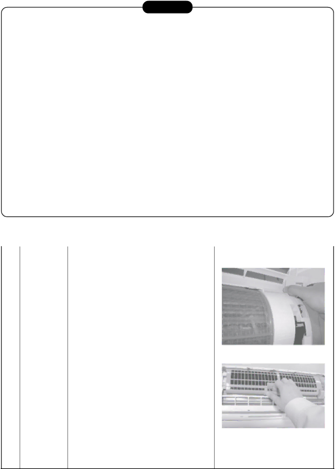
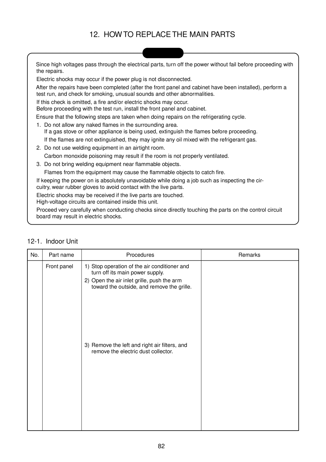
Part name Procedures Remarks
HOW to Replace the Main Parts
12-1 Indoor Unit
How to assemble the front panel
How to assemble the high voltage generator
How to assemble the electric parts box
Drain pan above the claws and at
Secure it
Raise the left side of the heat exchanger
Remove the two screws used to secure Bearing base
Slightly, and remove the bearing base
Secure using the fixing screw Screw Motor band Right
Drain pipe
Microcomputer
Part name Procedure Remarks
Board layout
Hands on the parts, etc
Wear gloves for this job
Otherwise, you may injure your
Attachment
Procedure Remarks Front cabinet Detachment
Some cases
Lead connected to compressor
Procedure
Terminal block
Disengage the four claws of the P.C. board base
Side cabinet left
With a burner
Take care to keep the 4-way valve away
Handling precaution
TS sensor Suction pipe temperature sensor
TE sensor outdoor heat exchanging temperature sensor
Shown in the above figure is
Part name Procedure
Parts name Qty Remarks
MCC-5009
Part Description
Exploded Views and Parts List
13-1 Indoor Unit
221 43047671 Pipe, Outlet
402 407, 408 403 404 406 410401 405
14, 15, 17, 18
104
13-3. P.C. Board Layout
Appendix-1
Required parts for installation work Recommendation
Part name ’ty Specifications/Vendor Remarks
Applicable Models RAS-10GAVP-E, RAS-13GAVP-E, RAS-16GAVP-E
Part name Specifications Usage
Required tools for installation work
Appendix-2
Cord heater installation wiring diagram
Appendix-3
Photo / Explanatory diagram Procedure
Cord heater installation work procedure
Appendix-4
Appendix-5
Used screw Screw type Quantity
Appendix-6
Appendix-7
Photo / Explanatory diagram Procedure Assembly
Appendix-8
Material SGCC-Z08, Thickness 0.8t Appendix-9
Drawing of thermostat fixing plate
Ø3.4 burring hole Upward Ø3.4 burring hole Downward
Appendix-10
Toshiba Carrier Corporation