WARNING |
Electrical Shock Hazard
Disconnect power before servicing.
Replace all parts and panels before operating.
Failure to do so can result in death or electrical shock.
DRIVE MOTOR | INTERLOCK SWITCH |
1
2
3
4
5
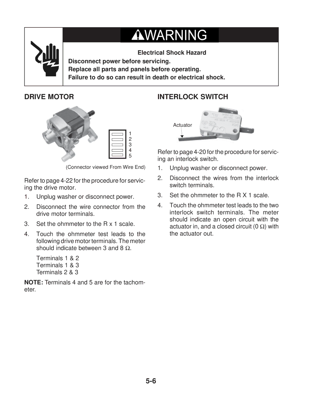
(Connector viewed From Wire End)
Refer to page
1.Unplug washer or disconnect power.
2.Disconnect the wire connector from the drive motor terminals.
3.Set the ohmmeter to the R x 1 scale.
4.Touch the ohmmeter test leads to the
following drive motor terminals. The meter should indicate between 3 and 8 Ω.
Terminals 1 & 2 Terminals 1 & 3 Terminals 2 & 3
Actuator
Refer to page
1.Unplug washer or disconnect power.
2.Disconnect the wires from the interlock switch terminals.
3.Set the ohmmeter to the R X 1 scale.
4.Touch the ohmmeter test leads to the two interlock switch terminals. The meter
should indicate an open circuit with the actuator in, and a closed circuit (0 Ω) with the actuator out.
NOTE: Terminals 4 and 5 are for the tachom- eter.
