PRODUCT OPERATION
THEORY OF OPERATION
INTRODUCTION
The Maytag Epic
WATER SYSTEM
The water system consists of the hot and cold water inlet valves, a water temperature sensor, a water flowmeter and control, and the dis- penser distribution system along with a tradi- tional pressure switch.
WATER INLET VALVES
The hot and cold water inlet valves are located at the back of the washer. These valves re- ceive a control signal from the Central Control Unit to manage the temperature of incoming water. The temperatures are determined by the specific wash cycle selected and a tem- perature sensor located in the wash tub. To improve cleaning of heavily soiled clothing and to provide a sanitizing feature, the water tem- perature can be increased through the use of a heating element located in the bottom of the tub.
FLOWMETER
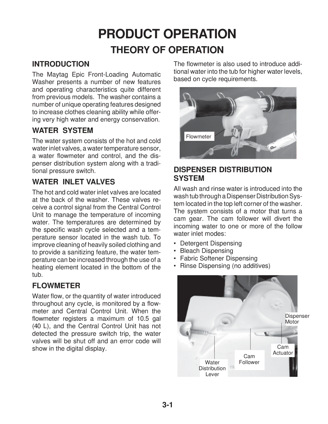
The flowmeter is also used to introduce addi- tional water into the tub for higher water levels, based on cycle requirements.
Flowmeter
DISPENSER DISTRIBUTION SYSTEM
All wash and rinse water is introduced into the wash tub through a Dispenser Distribution Sys- tem located in the top left corner of the washer. The system consists of a motor that turns a cam gear. The cam follower will divert the incoming water to one or more of the follow water inlet modes:
•Detergent Dispensing
•Bleach Dispensing
•Fabric Softener Dispensing
•Rinse Dispensing (no additives)
Water flow, or the quantity of water introduced throughout any cycle, is monitored by a flow- meter and Central Control Unit. When the flowmeter registers a maximum of 10.5 gal (40 L), and the Central Control Unit has not detected the pressure switch trip, the water valves will be shut off and an error code will show in the digital display.
Cam
Dispenser
Motor
Cam
Actuator
Water Follower
Distribution
Lever
