134 |
|
| Appendix A: Troubleshooting | ||
|
|
|
|
| |
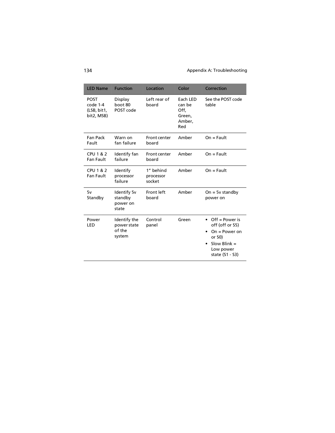
LED Name | Function | Location | Color | Correction |
|
|
|
|
|
|
|
POST | Display | Left rear of | Each LED | See the POST code | |
code | boot 80 | board | can be | table | |
(LSB, bit1, | POST code |
| Off, |
|
|
bit2, MSB) |
|
| Green, |
|
|
|
|
| Amber, |
|
|
|
|
| Red |
|
|
|
|
|
|
|
|
Fan Pack | Warn on | Front center | Amber | On = Fault | |
Fault | fan failure | board |
|
|
|
|
|
|
|
|
|
CPU 1 & 2 | Identify fan | Front center | Amber | On = Fault | |
Fan Fault | failure | board |
|
|
|
|
|
|
|
|
|
CPU 1 & 2 | Identify | 1” behind | Amber | On = Fault | |
Fan Fault | processor | processor |
|
|
|
| failure | socket |
|
|
|
|
|
|
|
|
|
5v | Identify 5v | Front left | Amber | On = 5v standby | |
Standby | standby | board |
| power on | |
| power on |
|
|
|
|
| state |
|
|
|
|
|
|
|
|
|
|
Power | Identify the | Control | Green | • Off = Power is | |
LED | power state | panel |
| off (off or S5) | |
| of the |
|
| • On = Power on | |
|
|
|
| ||
system | or S0) |
| |
| • Slow Blink = |
| Low power |
| state (S1 - S3) |
|
|