170 | Appendix F: Diagnostic Code Checkpoints |
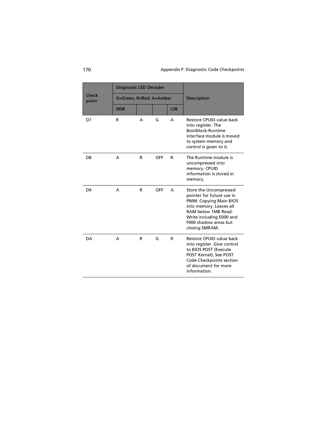
Check point
Diagnostic LED Decoder
G=Green, R=Red, A+Amber
MSB |
|
| LSB |
|
|
|
|
Description
D7 | R | A | G | A | Restore CPUID value back |
|
|
|
|
| into register. The |
|
|
|
|
| |
|
|
|
|
| interface module is moved |
|
|
|
|
| to system memory and |
|
|
|
|
| control is given to it. |
|
|
|
|
|
|
D8 | A | R | OFF | R | The Runtime module is |
|
|
|
|
| uncompressed into |
|
|
|
|
| memory. CPUID |
|
|
|
|
| information is stored in |
|
|
|
|
| memory. |
|
|
|
|
|
|
D9 | A | R | OFF | A | Store the Uncompressed |
|
|
|
|
| pointer for future use in |
|
|
|
|
| PMM. Copying Main BIOS |
|
|
|
|
| into memory. Leaves all |
|
|
|
|
| RAM below 1MB Read- |
|
|
|
|
| Write including E000 and |
|
|
|
|
| F000 shadow areas but |
|
|
|
|
| closing SMRAM. |
|
|
|
|
|
|
DA | A | R | G | R | Restore CPUID value back |
|
|
|
|
| into register. Give control |
|
|
|
|
| to BIOS POST (Execute |
POST Kernel). See POST Code Checkpoints section of document for more information.