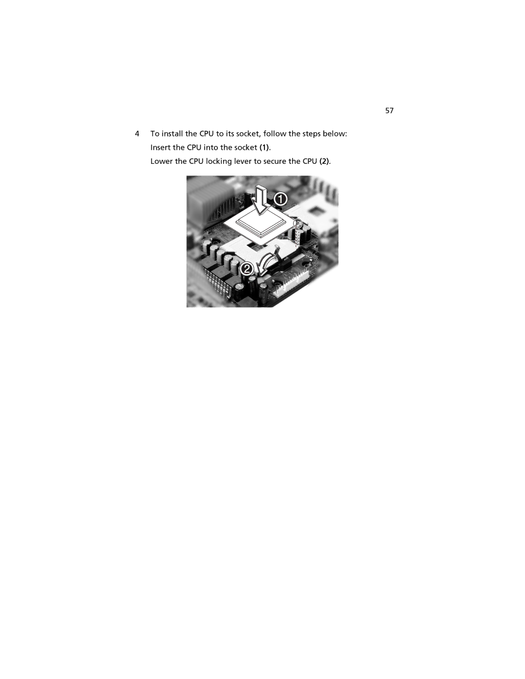
User’s guide
Acer Altos G520 series
Copyright 2004 Acer Incorporated All Rights Reserved
Acer Altos G520 series User’s guide 1st Issue July
Model Number Serial Number Purchase Date Place of Purchase
FCC notice
Notices
Class B equipment
Laser compliance statement
Important safety instructions
e If the product has been dropped or the cabinet has been damaged
1 System tour
2 System setup
Contents
3 Upgrading the system
4 BIOS setup
Appendix A Troubleshooting
Appendix B ASM Quick Installation Guide135
1 System tour
Page
Storage
Product briefing
Processor
Memory subsystem
Serial ATA ports
Graphics interface
Networking
I/O ports
Caring features
Product specification summary
Front bezel
External and internal structure
1 System tour
Front panel
Altos G520 with Hot Plug hard disk cage installed
Altos G520 with non-Hot Plug hard disk cage installed
No. Description 1 CD-ROM drive Stop/Eject button
1 System tour
Rear panel
Altos G520 with redundant power supply unit installed
Altos G520 with fixed single power supply unit installed
1 This indicator will light up green when the power supply module is functioning properly
1 System tour
Internal components
Altos G520 with Hot Plug hard disk cage installed
Altos G520 with non-Hot Plug hard disk cage installed
1 Though the system supports two hot-swappable power supply modules, the sys- tem comes bundled with a single standard 600-watt power supply module only. You have the option to purchase an extra power supply module to provide the sys- tem with a redundant power source
Mainboard layout
System boards
+12V CPU power connector
Note Unless otherwise indicated, all mainboard features
Auxilliary power connector
Main power connector
Floppy drive connector
ATA power connector
BIOS select jumper
IPMB connector
4 SCSI HDD management cable connector I2C bus
Hot Plug HDD Cage backplane board layout SCSI
LabelDescription 1 122-pin SAF-TE connector
2 80-pin SCSI HDD connector 3 68-pin SCSI HDD connector
Label
Hot Plug HDD Cage backplane board layout SATA
Power connector
1 System tour
3 HDD backplane power connector 10pin
LabelDescription 2 SATA cable connector
1 System tour
2 System setup
Page
Selecting a site
Setting up the system
Preinstallation requirements
Checking the package contents
To connect the PS/2 keyboard
Connecting peripherals
To connect the PS/2 mouse
VGA/monitor port blue port located on the rear panel of the server
To connect the VGA monitor
2 System setup
To connect the VGA monitor, simply plug the monitor cable into the
To connect the power cable
Turning on the system
Power-on problems
Operating system configuration
To connect to the network, simply plug the network cable into the
Network connection
Gigabit LAN port gray port
Tower-to-rack option
Turning off the system
2 System setup
3 Upgrading the system
Page
Upgrading the system
Installation precautions
ESD precautions
Preinstallation instructions
Post-installation instructions
To remove the front bezel
Opening the server
Before opening the server
To open the front bezel
3 Lift it up a little 1, then move it away from the chassis
2 Open it approximately
3 Upgrading the system
To remove the side panel
3 Upgrading the system
2 Pull out the air baffle to remove it from the chassis
To remove the Hot Plug HDD cage
Configuring the Hot Plug HDD cage
3 Upgrading the system
b SATS HDD power cable
4 Loosen the four thumbscrews that secure the cage to the chassis
5 Pull the cage from the chassis
To install a hard disk into the carrier
To install the Hot Plug HDD cage
b SATA HDD power cable
c SCSI HDD power cable
6 Reinstall the air baffle and the chassis panels
To remove the cage
Configuring the non-Hot Plug HDD cage
To install a hard disk into the cage
To install the cage
To remove a 5.25-inch storage device
Installing and removing storage devices
To install a 5.25-inch storage device
4 Observe the post-installation instructions described on page
3 Connect the power and bus cables to the new drive
3 Upgrading the system
To remove a CPU with heatsink
Upgrading the CPU
Processor Sequence
To install a CPU with heatsink
Lower the CPU locking lever to secure the CPU
3 Upgrading the system
6 Observe the post-installation instructions described on page
5 Replace the heatsink on top of the CPU
Plug the CPU fan in to the mainboard
Upgrading the system memory
To remove a DIMM
To install a DIMM
Reconfiguring the system memory
Replacing the Backup Battery
12 Attach the AC power cord
To install an expansion card
Installing an expansion card
6 Align the card in an empty slot on the mainboard
9 Observe the post-installation instructions described on page
Installing a redundant power supply module
To install a redundant power supply module
3 Upgrading the system
4 BIOS setup
Page
BIOS setup
Entering BIOS setup
Press F10 to save changes and close the BIOS setup
Press F1 for General Help on using the BIOS setup
Press Esc to close the BIOS setup
Main
Select the language used by BIOS. Choose from
Configures the system time in 24hour format
Configures the system date
Default value is Build Date
Advanced
Processor Summary and Configuration
IDE Configuration
A1-3
Primary/Secondary/Third/Fourth IDE Master/Slave
Selects DMA Direct Memory Access
Block Multi- Sector Trans- fer Mode
Parameter
Floppy Configuration
Super I/O Configuration
USB Configuration
Parameter
PCI Configuration
Memory Configuration
Enabled
When enabled, BIOS will activate and
Disabled
retest all DIMMs on next boot. Automati
4 BIOS setup
Boot
Boot Settings Configuration
Boot Device Priority
boot up when previoius attempts fail
1st Boot Device
attempt to boot up
Boot Device
4 BIOS setup
Hard Disk Drives
Removable Devices
4 BIOS setup
ATAPI CD/DVD Devices
Security
Parameter
To remove the User password
To set an Administrator/User password
The Server menu allows you to configure the system parameters
Server
Power On
When set to Stays Off, Front Panel Switch
Power Loss
Inhibit in BIOS Security menu is disabled
4 BIOS setup
System Management
Serial Console Features
Parameter
Event Log Configuration
Parameter
Exit
Defaults
Loads the custom settings for all BIOS parameters as
Defaults
Saves custom settings for all BIOS parameters
Obtaining the Upgrade
Upgrading the BIOS
Preparing for the Upgrade
Recording the Current BIOS Settings
Creating the BIOS Upgrade Diskette
Creating a Bootable Diskette
Upgrading the BIOS
3 If you selected option 1, to automatically update the system BIOS
Recovering the BIOS
Changing the BIOS Language
Manually Recovering the BIOS
Clearing the CMOS
Clearing the Password
BIOS Error Messages
Error Message
BIOS POST Beep Codes
BIOS Recovery Beep Codes
Configuration and BIOS Select Jumpers
What happens at system reset
Appendix A Troubleshooting
Page
Problems following Initial System Installation
Resetting the System
First Steps Checklist
Hardware Diagnostic Testing
Confirming Loading of the Operating System
Verifying Proper Operation of Key System Lights
Power Light Does Not Light
Specific Problems and Corrective Actions
No Characters Appear on Screen
System Cooling Fans Do Not Rotate Properly
Characters Are Distorted or Incorrect
Optical Drive Activity Light Does Not Light
Diskette Drive Activity Light Does Not Light
The controller stopped working when an add-in adapter was installed
Problems with Network
The server hangs when the drivers are loaded
Diagnostics pass but the connection fails
Problems with Newly Installed Application Software
System Boots when Installing PCI Card
The add-in adapter stopped working without apparent cause
Hard Drives are not Recognized
Problems with Application that Ran Correctly Earlier
LED Information
Bootable CD-ROM Is Not Detected
Appendix A Troubleshooting
Appendix B ASM Quick Installation Guide
This appendix shows you how to install the ASM software package
System requirements
Installing ASM
System setup
Installing ASM Agent
Appendix B ASM Quick Installation Guide
Installing ASM Console
Appendix C Altos
G520 Rack Installation Guide
Page
System rack installation
Vertical mounting hole pattern
Screw types for rack installation
Installing the system into the rack
To install cage nuts
Installing cage nuts
5 Extend the middle sliding piece of each mounting rail forward until it clicks
Appendix D SATA RAID Configuration
This appendix shows you how to create SATA RAID
Loading onboard SATA RAID default setting
Configuring the onboard SATA RAID
How to enable the onboard SATA RAID function
How to create RAID 1 volume
Initial RAID Volume
Create RAID 1 volume
Save and Exit Embedded RAID Configuration Utility
Appendix D SATA RAID Configuration
Appendix E RAID Configuration
This appendix shows you how to create RAID
Loading HBA Default Settings
Configuring the SCSI/SCSI RAID HBA
How to use SCSI HBA setup utility
How to use SCSI RAID HBA setup utility
Exit and Restart the server
MegaRAID Configuration Utility
RAID Volume Initialization
Load RAID Card Default Setting
Initialize RAID Volume
Create RAID1 Volume
Assign Hot Spare Disk
Save And Exit MegaRAID Configuration Utility
Appendix F Diagnostic Code Checkpoints
Page
POST Code Checkpoints
Enable IRQ-0 in PIC for
Appendix F Diagnostic Code Checkpoints
Diagnostic LED Decoder
system timer. Install the
Diagnostic LED Decoder
Initializes the silent boot
Appendix F Diagnostic Code Checkpoints
Diagnostic LED Decoder
adapter installed in the
Diagnostic LED Decoder Check
Appendix F Diagnostic Code Checkpoints
Diagnostic LED Decoder
Bootblock Initialization Code Checkpoints
Diagnostic LED Decoder
Bootblock-Runtime
Appendix F Diagnostic Code Checkpoints
Diagnostic LED Decoder G=Green, R=Red, A+Amber
Restore CPUID value back
Bootblock Recovery Code Checkpoint
recovery file name in root
Appendix F Diagnostic Code Checkpoints
Diagnostic LED Decoder G=Green, R=Red, A=Amber
Read error occured on
Check point
Appendix F Diagnostic Code Checkpoints
Index