|
|
|
|
|
|
|
|
|
|
|
|
|
|
|
| |||
|
|
|
|
|
|
|
|
|
|
|
|
|
|
|
|
|
| |
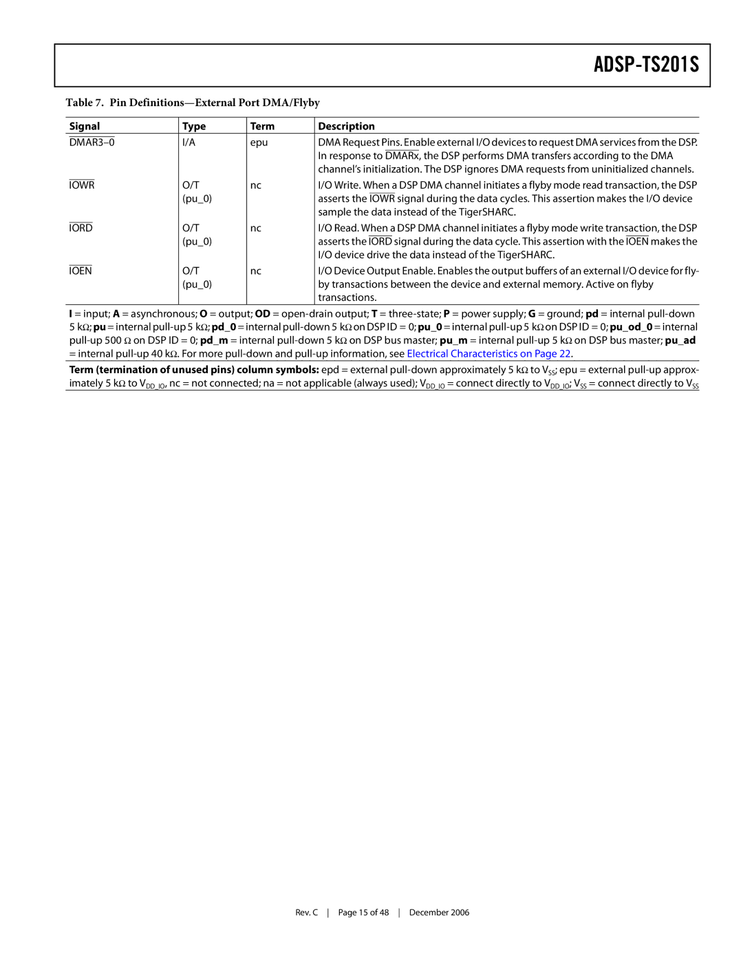
| Table 7. Pin | |||||||||||||||||
|
|
|
|
|
|
|
| |||||||||||
|
| Signal |
| Type | Term | Description |
| |||||||||||
|
|
|
|
|
|
| I/A | epu | DMA Request Pins. Enable external I/O devices to request DMA services from the DSP. | |||||||||
|
| |||||||||||||||||
|
|
|
|
|
|
|
|
| In response to | DMARx, | the DSP performs DMA transfers according to the DMA | |||||||
|
|
|
|
|
|
|
|
| channel’s initialization. The DSP ignores DMA requests from uninitialized channels. | |||||||||
|
|
|
|
|
|
| O/T | nc | I/O Write. When a DSP DMA channel initiates a flyby mode read transaction, the DSP | |||||||||
IOWR | ||||||||||||||||||
|
|
|
|
|
|
| (pu_0) |
| asserts the | IOWR | signal during the data cycles. This assertion makes the I/O device | |||||||
|
|
|
|
|
|
|
|
| sample the data instead of the TigerSHARC. | |||||||||
|
|
|
|
|
| O/T | nc | I/O Read. When a DSP DMA channel initiates a flyby mode write transaction, the DSP | ||||||||||
IORD | ||||||||||||||||||
|
|
|
|
|
|
| (pu_0) |
| asserts the | IORD | signal during the data cycle. This assertion with the | IOEN | makes the | |||||
|
|
|
|
|
|
|
|
| I/O device drive the data instead of the TigerSHARC. | |||||||||
|
|
|
|
| O/T | nc | I/O Device Output Enable. Enables the output buffers of an external I/O device for fly- | |||||||||||
IOEN | ||||||||||||||||||
|
|
|
|
|
|
| (pu_0) |
| by transactions between the device and external memory. Active on flyby | |||||||||
|
|
|
|
|
|
|
|
| transactions. |
| ||||||||
I = input; A = asynchronous; O = output; OD =
5kΩ; pu = internal
Term (termination of unused pins) column symbols: epd = external
Rev. C Page 15 of 48 December 2006