ADSP-TS201S
Link Port—Data In Timing
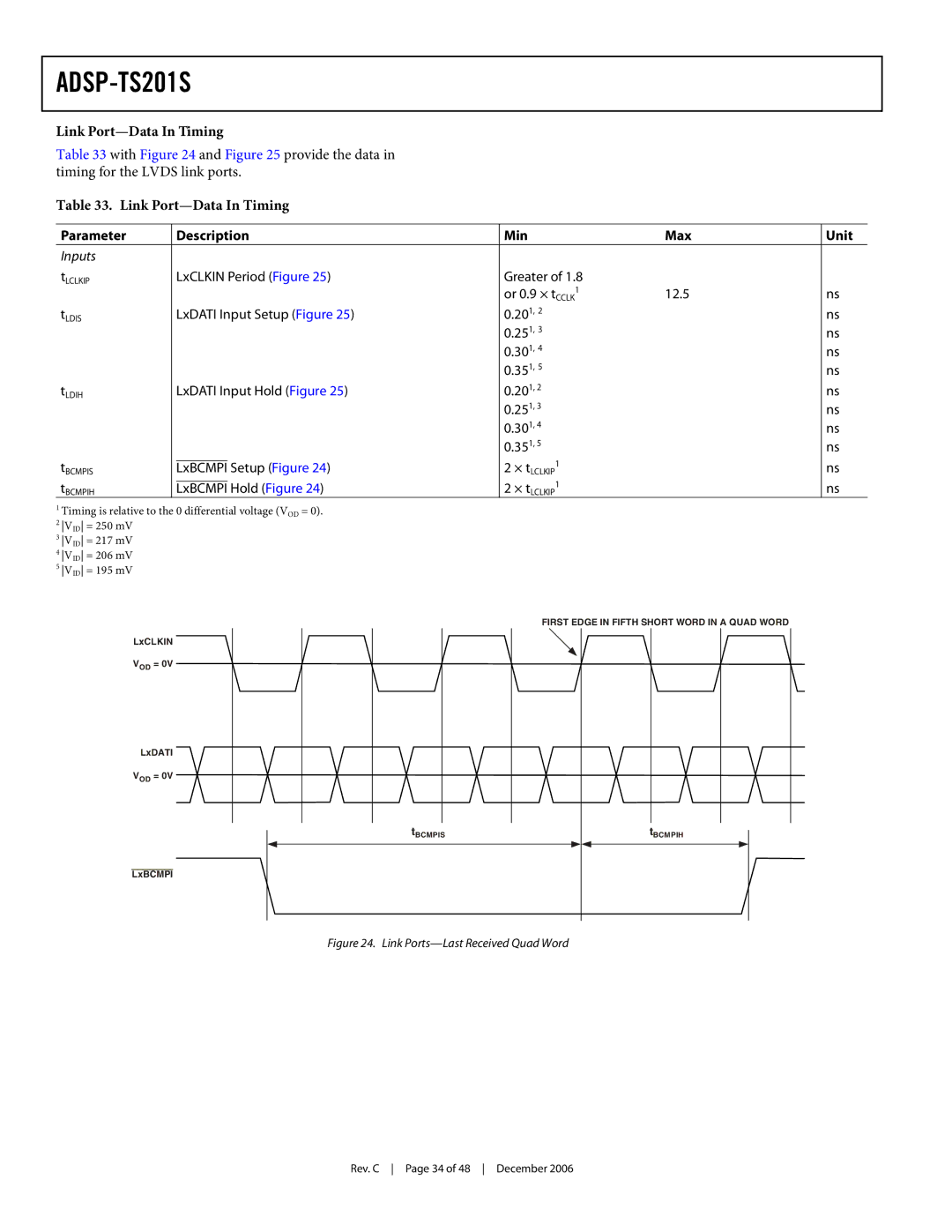
Table 33 with Figure 24 and Figure 25 provide the data in timing for the LVDS link ports.
Table 33. Link
Parameter |
| Description | Min | Max | Unit | |
Inputs |
|
|
|
|
|
|
tLCLKIP |
| LxCLKIN Period (Figure 25) | Greater of 1.8 |
|
| |
|
|
|
| 1 | 12.5 | ns |
|
|
|
| or 0.9 × tCCLK | ||
tLDIS |
| LxDATI Input Setup (Figure 25) | 0.201, 2 |
| ns | |
|
|
|
| 0.251, 3 |
| ns |
|
|
|
| 0.301, 4 |
| ns |
|
|
|
| 0.351, 5 |
| ns |
tLDIH |
| LxDATI Input Hold (Figure 25) | 0.201, 2 |
| ns | |
|
|
|
| 0.251, 3 |
| ns |
|
|
|
| 0.301, 4 |
| ns |
|
|
|
| 0.351, 5 |
| ns |
tBCMPIS |
|
|
| 1 |
|
|
| LxBCMPI Setup (Figure 24) |
| ns | |||
| 2 × tLCLKIP |
| ||||
tBCMPIH |
|
|
| 1 |
|
|
| LxBCMPI Hold (Figure 24) |
| ns | |||
| 2 × tLCLKIP |
| ||||
1Timing is relative to the 0 differential voltage (VOD = 0).
2 VID = 250 mV
3 VID = 217 mV
4 VID = 206 mV
5 VID = 195 mV
FIRST EDGE IN FIFTH SHORT WORD IN A QUAD WORD
LxCLKIN
VOD = 0V
LxDATI
VOD = 0V
tBCMPIS
tBCMPIH
LxBCMPI
Figure 24. Link Ports—Last Received Quad Word
Rev. C Page 34 of 48 December 2006
