ADSP-TS201S
OUTLINE DIMENSIONS
The
1.25
1.00
0.75
25.20 |
25.00 |
24.80 |
A1 BALL |
INDICATOR |
24 | 22 | 20 | 18 | 16 | 14 | 12 | 10 | 8 | 6 | 4 |
| 2 | ||||||
23 | 21 | 19 | 17 | 15 | 13 | 11 | 9 | 7 | 5 | 3 | 1 | |||||||
1.00 BSC
23.00
A
B
C
D
E
F
G
H
J
K
25.20
BSC
L
M
25.00
SQ
N
P
1.25 |
|
1.00 |
|
0.75 | TOP VIEW |
24.801.00 BSC
(BALL
PITCH)
1.00![]()
![]()
BSC
BOTTOM VIEW
R
T
U
V
W
Y
AA
AB
AC
AD
3.10 |
|
2.94 | DETAIL A |
2.78 |
|
| 0.97 BSC |
NOTES: |
|
1. ALL DIMENSIONS ARE IN MILLIMETERS. | SEATING PLANE |
2.THE ACTUAL POSITION OF THE BALL GRID IS WITHIN 0.25 mm OF ITS IDEAL POSITION RELATIVE TO THE PACKAGE EDGES.
3.CENTER DIMENSIONS ARE NOMINAL.
4.THIS PACKAGE C ONFORMS TO JEDEC
1.60 MAX
0.60
0.50
0.40
0.75 |
|
|
|
| |||
|
|
|
| ||||
|
|
| 0.65 |
|
| 0.20 MAX | |
|
|
|
|
|
| ||
0.55 |
|
| |||||
|
|
|
| ||||
|
| (BALL |
|
| |||
DIAMETER) |
|
| |||||
DETAIL A
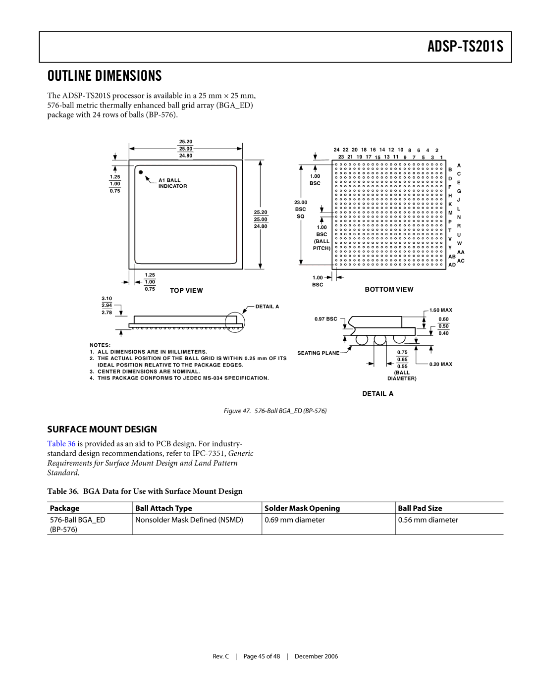
Figure 47. 576-Ball BGA_ED (BP-576)
SURFACE MOUNT DESIGN
Table 36 is provided as an aid to PCB design. For industry- standard design recommendations, refer to
Table 36. BGA Data for Use with Surface Mount Design
Package | Ball Attach Type | Solder Mask Opening | Ball Pad Size |
| Nonsolder Mask Defined (NSMD) | 0.69 mm diameter | 0.56 mm diameter |
|
|
|
|
Rev. C Page 45 of 48 December 2006
