ADSP-TS201S
STRAP PIN FUNCTION DESCRIPTIONS
Some pins have alternate functions at reset. Strap options set DSP operating modes. During reset, the DSP samples the strap option pins. Strap pins have an internal
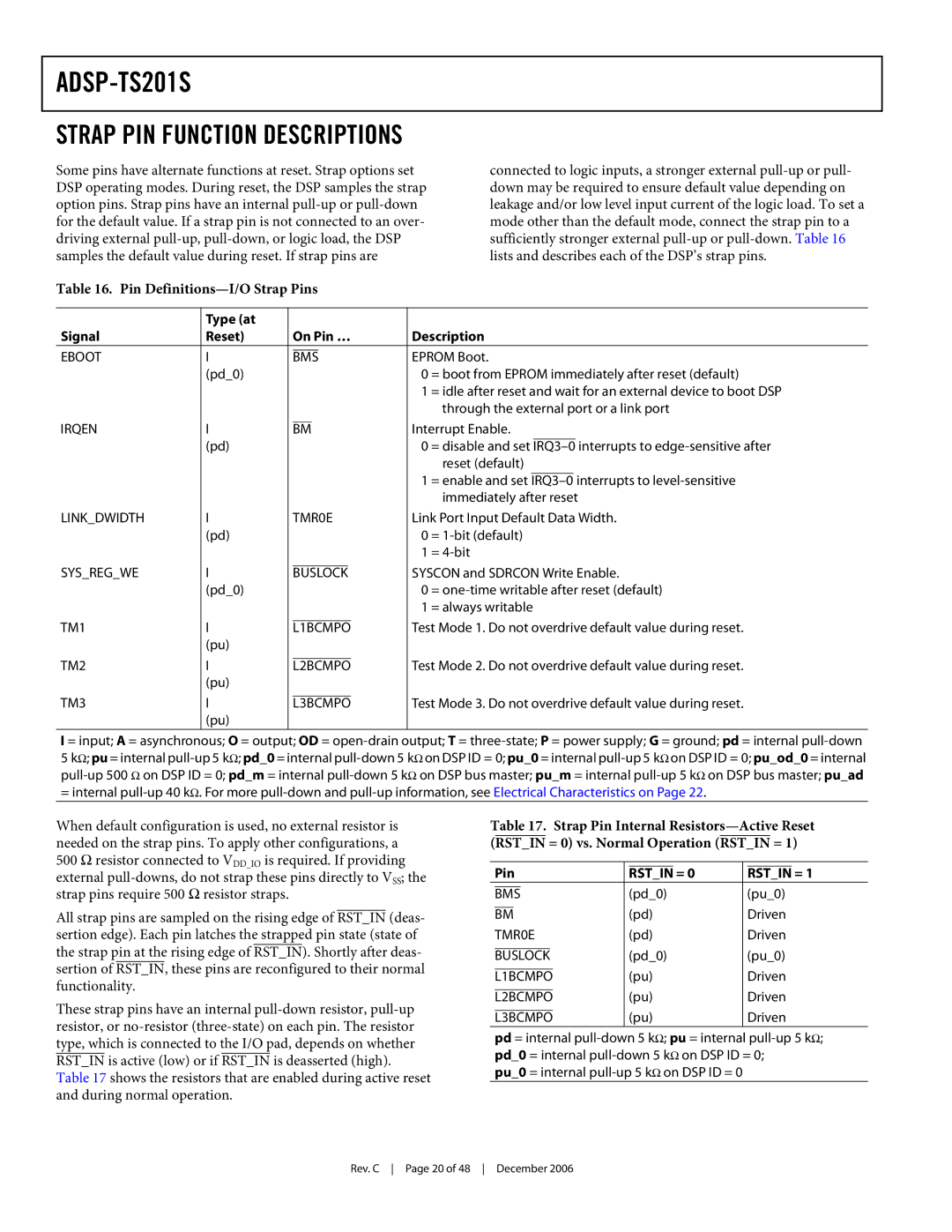
Table 16. Pin Definitions—I/O Strap Pins
connected to logic inputs, a stronger external
| Type (at |
|
|
|
|
|
|
|
|
|
|
|
|
Signal | Reset) | On Pin … |
| Description | |||||||||
EBOOT | I |
|
|
|
|
|
| EPROM Boot. | |||||
| BMS | ||||||||||||
| (pd_0) |
|
|
|
|
|
| 0 | = boot from EPROM immediately after reset (default) | ||||
|
|
|
|
|
|
|
| 1 | = idle after reset and wait for an external device to boot DSP | ||||
|
|
|
|
|
|
|
|
| through the external port or a link port | ||||
IRQEN | I |
|
|
|
|
| Interrupt Enable. | ||||||
BM | |||||||||||||
| (pd) |
|
|
|
|
|
| 0 | = disable and set | interrupts to | |||
|
|
|
|
|
|
|
|
| reset (default) | ||||
|
|
|
|
|
|
|
| 1 | = enable and set | interrupts to | |||
|
|
|
|
|
|
|
|
| immediately after reset | ||||
LINK_DWIDTH | I |
| TMR0E |
| Link Port Input Default Data Width. | ||||||||
| (pd) |
|
|
|
|
|
| 0 | = | ||||
|
|
|
|
|
|
|
| 1 | = | ||||
SYS_REG_WE | I |
|
|
|
| SYSCON and SDRCON Write Enable. | |||||||
| BUSLOCK | ||||||||||||
| (pd_0) |
|
|
|
|
|
| 0 | = | ||||
|
|
|
|
|
|
|
| 1 | = always writable | ||||
TM1 | I |
|
|
| Test Mode 1. Do not overdrive default value during reset. | ||||||||
L1BCMPO | |||||||||||||
| (pu) |
|
|
|
|
|
|
|
|
|
|
|
|
TM2 | I |
|
|
| Test Mode 2. Do not overdrive default value during reset. | ||||||||
L2BCMPO | |||||||||||||
| (pu) |
|
|
|
|
|
|
|
|
|
|
|
|
TM3 | I |
|
|
| Test Mode 3. Do not overdrive default value during reset. | ||||||||
L3BCMPO | |||||||||||||
| (pu) |
|
|
|
|
|
|
|
|
|
|
|
|
I = input; A = asynchronous; O = output; OD =
5kΩ; pu = internal
When default configuration is used, no external resistor is needed on the strap pins. To apply other configurations, a
500 Ω resistor connected to VDD_IO is required. If providing external
All strap pins are sampled on the rising edge of RST_IN (deas- sertion edge). Each pin latches the strapped pin state (state of the strap pin at the rising edge of RST_IN). Shortly after deas- sertion of RST_IN, these pins are reconfigured to their normal functionality.
These strap pins have an internal
Table 17 shows the resistors that are enabled during active reset and during normal operation.
Table 17. Strap Pin Internal
|
|
|
|
|
|
|
|
|
|
|
|
| Pin |
| RST_IN = 0 |
| RST_IN = 1 | ||||||
|
|
|
|
|
|
| (pd_0) | (pu_0) | |||
| BMS | ||||||||||
|
|
|
|
|
| (pd) |
| Driven | |||
| BM |
| |||||||||
| TMR0E |
| (pd) |
| Driven | ||||||
|
|
|
|
| (pd_0) | (pu_0) | |||||
| BUSLOCK | ||||||||||
|
|
|
| (pu) |
| Driven | |||||
| L1BCMPO |
| |||||||||
|
|
|
| (pu) |
| Driven | |||||
| L2BCMPO |
| |||||||||
|
|
|
| (pu) |
| Driven | |||||
| L3BCMPO |
| |||||||||
pd = internal
pu_0 = internal
Rev. C Page 20 of 48 December 2006