Audix
Comments
Contents
Static Access Dynamic Access
232
Modems
For DCP
Switch or Customer Requirements for DCP Mode
Contents
Considerations General Information
Rack-Mount Equipment Cabling
DIP Switch Settings
Systems Non-DCP Switch Applications
System 85 Administration Generic 2 Administration
4ESS Administration
Loopback Testing for R1V7
Modem Pooling Testing
Partial Updates
Complete Updates
Audix Network Testing
Network Turnaround
Network Considerations
Systems
Sales Engineering Notes
Index
List of Figures
Only
Male Connector
Xii Contents
Cable
Assignments
Network Port Form
System Limits Form
System
Around
Local Connection Test
Local Connection Failure
Remote Connection Test
Remote Connection Failure
List of Tables
Xvi Contents
About This Document
Intended Audience
Prerequisite Skills or Knowledge
HOW this Document is Organized
Changes from the Previous Issue
Xviii About This Document
Conventions Used in this Document
Trademarks and Service Marks
About This Document
Related Resources
HOW to Make Comments about this Document
Xx About This Document
Introduction
Network Interface
Local Networking
2Introduction
Remote Networking
Network Planning
Audix Network Implementation
Introduction
Audix Software
4Introduction
TN539 Acce
Rear Connector Panel and Backplane
Other Audix Circuit Pack Requirements
One-Cabinet and Two-Cabinet Audix System
Audix Large System
Network Cabling Common to Most Configurations
Rear Connector Panel and Backplane Large
H600-330, Group 1 Cable
Pin Number ⎜Connector ⎜50-Pin Amphenol
H600-331, Group 2 Cable
⎜RS-232 a ⎜50-Pin Amphenol
⎜RS-232 B
H600-331, Group 1 Cable
H600-331, Group 2 Audix Networking Breakout Cable
Pin Number ⎜Connector ⎜50 Pin Amphenol
⎜RS-232 a ⎜50 Pin Amphenol
⎜RS-232 B ⎜50 Pin Amphenol ⎜DCP
10Introduction
Networking Enhancements
Audix System Administration
R1V5 Release
R1V7 Release
R1V6 Release
12Introduction
Considerations
Dedicated EIA RS-232 Networks
General Information
Dedicated RS-232 Network of Two Audix Systems
2Dedicated EIA RS-232 Networks
Dedicated EIA RS-232 Networks
Call Detail Recording
Audix Requirements for Dedicated RS-232
4Dedicated EIA RS-232 Networks
Switch or Customer Requirements for Dedicated RS-232
Data Rates for Dedicated RS-232
Dedicated RS-232 Extended Connections
6Dedicated EIA RS-232 Networks
Switched EIA RS-232 Networks
Switched RS-232 Using Modems
2Switched EIA RS-232 Networks
Dedicated and Switched RS-232 Network for a Single Switch
Switched EIA RS-232 Networks
Audix System Requirements For Switched RS-232 Using Modems
4Switched EIA RS-232 Networks
ALL Connections to Analog Ports Modem Switch
Data Rates for Switched RS-232 Using Modems
6Switched EIA RS-232 Networks
Switched RS-232 Using Data Modules for DCP
DCP
Data Rates for Switched RS-232 Using Data Modules For DCP
8Switched EIA RS-232 Networks
DCP Mode 1 Networks 56 Kbps
2DCP Mode 1 Networks 56 Kbps
DCP Mode 1 Network Using Switched 56 Service
DCP Mode 1 Networks 56 Kbps
Dynamic Access
Static Access
4DCP Mode 1 Networks 56 Kbps
Audix System Requirements for DCP Mode
PC Added to a DCP Network
Static Access Switch Requirements
Switch or Customer Requirements for DCP Mode
6DCP Mode 1 Networks 56 Kbps
Data Rates for DCP Mode
Dynamic Access Switch Requirements
8DCP Mode 1 Networks 56 Kbps
DCP Mode 2 Networks Modem Pooling
Typical Rack-Mounted Modem Pool Using D-Lead Control
2DCP Mode 2 Networks Modem Pooling
DCP Mode 2 Networks Modem Pooling
To the Cross Connect Field DCP
DCP Mode 2 Network Modem Pooling
4DCP Mode 2 Networks Modem Pooling
Audix System Requirements for DCP Mode
6DCP Mode 2 Networks Modem Pooling
Basic Switch Needs
DCP Interface for the Audix Network Channels
DCP Interface for the Digital Side of the Modem Pool
Analog Interface for the Analog Side of the Modem Pool
8DCP Mode 2 Networks Modem Pooling
Modems and Data Modules
RS-232 Modems Modem Pool
10DCP Mode 2 Networks Modem Pooling
Rack-Mount Equipment
DCP Mode 2 for a 5ESS Switch
Cabling
12DCP Mode 2 Networks Modem Pooling
DCP Mode 3 Networks 64 Kbps
2DCP Mode 3 Networks 64 Kbps
DCP Mode 3 Network for a Single Switch
DCP Mode 3 Networks 64 Kbps
4DCP Mode 3 Networks 64 Kbps
Colocated Requirements
Interlocation Requirements
∙ Merlin II for colocated systems only
6DCP Mode 3 Networks 64 Kbps
This arrangement operates at speeds of 64 Kbps
DCP Mode 3 for a 5ESS Switch
DCP Mode 3 Network for a 5ESS Switch
8DCP Mode 3 Networks 64 Kbps
Mixtures of RS-232 and DCP Networks
RS-232 and DCP AT the Same Audix System
RS-232 and DCP AT Separate Locations
2Mixtures of RS-232 and DCP Networks
High-Speed Switched RS-232 and DCP Audix Connections
Mixtures of RS-232 and DCP Networks
Using DCP for Audix Systems and RS-232 for a PC
4Mixtures of RS-232 and DCP Networks
RS-232 and DCP at Separate Locations
6Mixtures of RS-232 and DCP Networks
EIA RS-232 Cabling
Dedicated RS-232 Cabling
EIA RS-232 Cabling
Male Or Connect to Another
Dedicated RS-232 Connection within 50 feet
Switched RS-232 Cabling
4EIA RS-232 Cabling
Switched RS-232 to an Analog Switch Port
ATI2
6EIA RS-232 Cabling
Mixing Modem Types and Modes
DIP Switch Settings
424 FS 424 MNP 3296 FS 3296 MNP
RS-232 to DCP Conversion
8EIA RS-232 Cabling
Switch Administration
MPDM/M1* Option Settings
10EIA RS-232 Cabling
Acce Wiring to the Switch
DCP Cabling and Administration
System 75, System 85, and Definity Communications Systems
Non-DCP Switch Applications
2DCP Cabling and Administration
DCP Cabling and Administration
4DCP Cabling and Administration
System 75, Generic 1, and Generic 3 Administration
Enter
System 85 Administration
6DCP Cabling and Administration
Xxxx0
8DCP Cabling and Administration
Fields
Generic 2 Administration
Manager III and Manager IV Administration
Manager II Administration
10DCP Cabling and Administration
Manager II Administration of DCP Port Proc 000, Word
12DCP Cabling and Administration
Call Types and Action Taken
Manager II Administration of DCP Port Proc 014, Word
Manager II Administration for DCP Ports Proc 051, Word
14DCP Cabling and Administration
Extension Appearance ID
16DCP Cabling and Administration
Switch Component Installation
DCP Mode 1 Installation and Administration
4ESS Administration
10-2DCP Mode 1 Installation and Administration
DCP Mode 1 Installation and Administration
10-4DCP Mode 1 Installation and Administration
Dial Access CODE/TRUNK ID Code
Modem Pooling
10-6DCP Mode 1 Installation and Administration
Timed Recall
Loopback Testing
Loopback Testing for R1V7
Setting Up the MPDM/M1
Loopback Testing for R1V5 and R1V6
10-8DCP Mode 1 Installation and Administration
Tx1 Rx1 Tx2 Rx2
10-10DCP Mode 1 Installation and Administration
Performing Loopback Test
Loopback Test with the H600-331, Group 2 Cable
10-12DCP Mode 1 Installation and Administration
Loopback Test with the H600-331, Group 1 Cable
DCP Mode 2 Installation and Administration
Installing a 2296A and Mtdm in a Modem Pool
Install the Modem Pool Cabinet
Install the Multiple Mountings
Install the Modems and Data Sets
11-2DCP Mode 2 Installation and Administration
DCP Mode 2 Installation and Administration
Modem Pooling Cabinet with MTDMs Front View
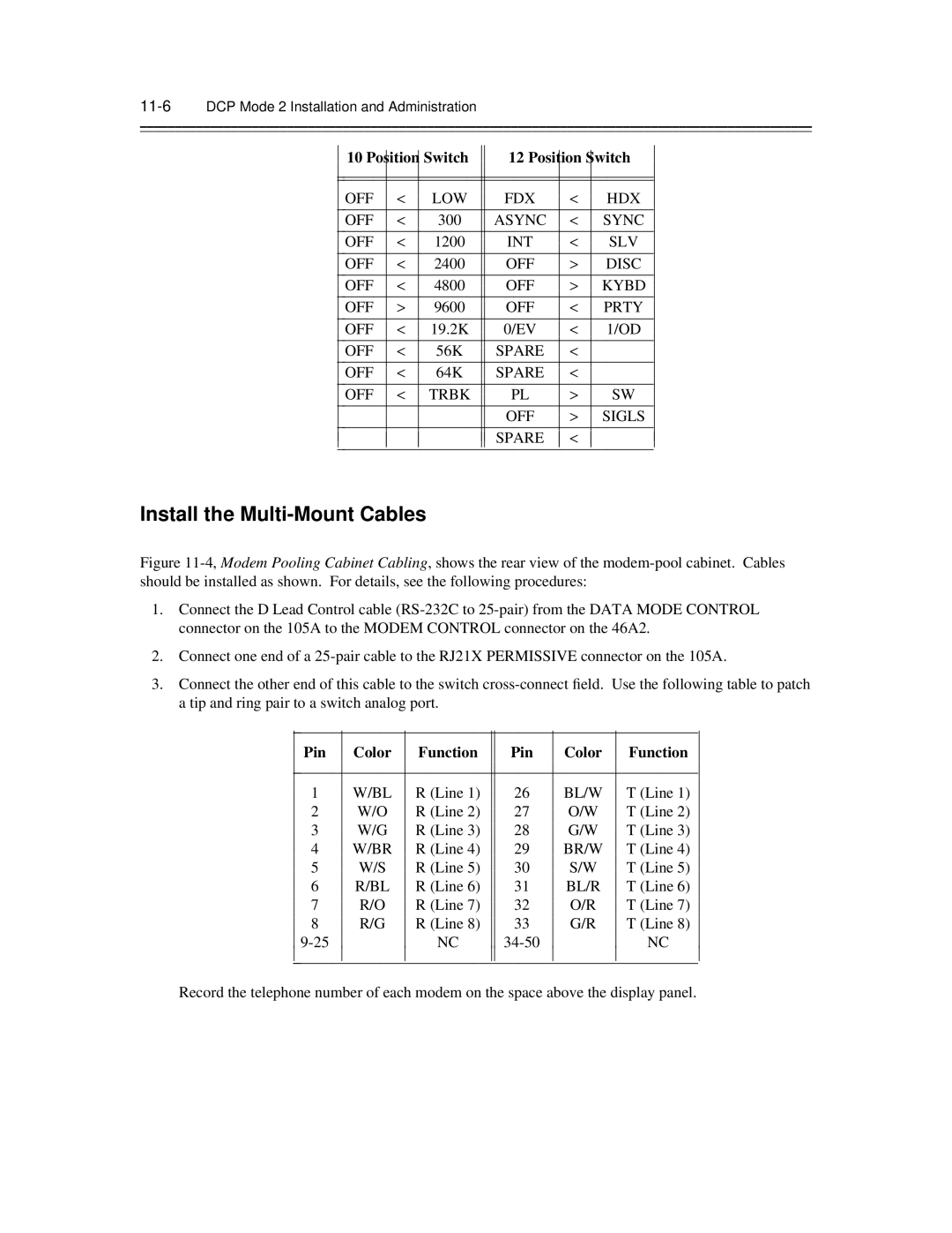
⎜ Switch ⎜ Position
Option Position ⎜ Switch
11-4DCP Mode 2 Installation and Administration
Verify That the Daughter Board Uses Tric 4 Chips Coded 229EJ
Install the Multi-Mount Cables
Position⎜ Switch⎜
11-6DCP Mode 2 Installation and Administration
Pin Color Function
Modem Pooling Cabinet Cabling
11-8DCP Mode 2 Installation and Administration
Color Function Pin ⎜ Pin
Install the Mtdm and 2296A Cables
2296A Option Settings D-Lead Modem Pool
11-10DCP Mode 2 Installation and Administration
Modem Pooling Cabinet with 7400As Front View
Installing a 7400A in a Modem Pool
11-12DCP Mode 2 Installation and Administration
Option and Value Screens ⎜ Set Option Screens
SN270B
Installing STAND-ALONE Modem Pools
11-14DCP Mode 2 Installation and Administration
2296A Modem Autocall Dialer Module, Type 2A4
Disassembling the Modem
11-16DCP Mode 2 Installation and Administration
2296A Modem Option Settings Stand-Alone Modem Pool
At&f x1 v0 m0 e0 &c1 &d2 &s1 s0=2 &w
DM424 Modem Option Settings Stand-Alone Modem Pool
Paradyne 3820 Modem Option Settings Stand-Alone Modem Pool
At&f *s0 *e0 &b2 x1 v0 m0 e0 &w
At&f0 &d2 &s1 \d3 \n0 e0 v0 x1 s41=3 s43=1 s76=1 s78=1 &w0
RS-232 Breakout Box
11-18DCP Mode 2 Installation and Administration
Stand-Alone Modem Cabling
7400A DSU Option Settings Stand-Alone Modem Pool
Option Setting
Administering the Switch for Modem Pooling
11-20DCP Mode 2 Installation and Administration
System 75, Generic 1, and Generic 3 Modem Pool Assignments
11-22DCP Mode 2 Installation and Administration
Modem Pooling Testing
Next Circuit
11-24DCP Mode 2 Installation and Administration
Trunk Group 130 Bearer Capability Class of Service
11-26DCP Mode 2 Installation and Administration
11-27
11-28DCP Mode 2 Installation and Administration
Trunk Group 131 Bearer Capability Class of Service
11-30DCP Mode 2 Installation and Administration
DCP Mode 3 Installation and Administration
12-2DCP Mode 3 Installation and Administration
Manager II Mode 3 Administration Proc 100, Word
DCP Mode 3 Installation and Administration
Loopback Testing for Interlocated Systems
12-4DCP Mode 3 Installation and Administration
64 Kbps Network Loop-Around Test
12-6DCP Mode 3 Installation and Administration
Remote Updates
Audix System Administration
Partial Updates
13-2AUDIX System Administration
Complete Updates
Network Turnaround
Audix System Administration
Setting UP the Local Audix System Profile
System Profiles
13-4AUDIX System Administration
Form Fields
13-5
13-6AUDIX System Administration
13-7
13-8AUDIX System Administration
13-9
13-10AUDIX System Administration
Setting UP a Remote Audix System Profile
Saving Local System Data
Form Fields
13-12AUDIX System Administration
13-13
13-14AUDIX System Administration
13-15
13-16AUDIX System Administration
Saving Remote System Data
Recording Audix Machine Names
Enter machine voice ID and pound sign
Administering Ports
13-18AUDIX System Administration
For each RS-232 channel cabled, set equipped to y
13-20AUDIX System Administration
Saving Data
13-22AUDIX System Administration
Administering System Limits
Calculating Filesystem Sizes
System Limits Form
Comparing the Recommended File Sizes to Actual Sizes
13-24AUDIX System Administration
Increasing the Size of a Filesystem
Moving a Subscriber Between Audix Systems in a Network
13-26AUDIX System Administration
ADMINISTRATOR’S Worksheet
Administrator Worksheet for Audix Networking
Blank Administrator Worksheet for Audix Networking
13-28AUDIX System Administration
Page
14-2AUDIX Network Testing
Press Enter to Refresh ACC Status Information
Maintenance Network Form R1V6
Audix Network Testing
Testing the Network Connections
Testing Remote DCP Connections
14-4AUDIX Network Testing
Performing Remote Connection Tests
Set select test to
14-6AUDIX Network Testing
Remote Connection Test Analog Path to Another Audix system
Remote Connection Test Colocated Audix system
Testing Remote Switched RS-232 Connections
14-8AUDIX Network Testing
Remote Connection Test RS-232 to Tip/Ring
14-10AUDIX Network Testing
Remote Connection Test RS-232 Colocated Audix system
Testing Remote Switched RS-232 Converted to DCP Connections
Made
14-12AUDIX Network Testing
10.Remote Connection Test RS-232 Converted to DCP
Testing Remote Dedicated RS-232 Connections
14-14AUDIX Network Testing
11.Remote Connection Test RS-232 Direct
Testing the Near-End Connection
Performing Loop-Around Tests
14-16AUDIX Network Testing
DS-1
13.Near End Connection Test CO DCP Analog Loop-Around
14-18AUDIX Network Testing
14.Near End Connection Test CO RS-232 Analog Loop-Around
Testing the Local Connection
14-20AUDIX Network Testing
15.Local Connection Test DCP
16.Local Connection Test Switched RS-232
14-22AUDIX Network Testing
17.Local Connection Test Dedicated RS-232
Testing the 56/64 Kbps Network Connection
14-24AUDIX Network Testing
18.56/64 Kbps Network Loop-Around Test
Channel Internal Loop-Around Test
Performing Channel or Modem Loop-Around Tests
Modem Loop-Around Test
Setting UP Remote Updates
Activating the Remote Updates Feature
Testing the Remote Updates Feature
Demand Update Procedure
Performing Voice Mail Test
Log In to the Remote Adjunct
Activating Remote Updates for Additional Audix Systems
14-28AUDIX Network Testing
Checking Administration LOG Entries
Troubleshooting the Network
14-30AUDIX Network Testing
19.Checking the Acce Board Status
14-32AUDIX Network Testing
20.Checking the Acce Channel Status
21.Checking the Acce Channel Status
14-34AUDIX Network Testing
22.Checking the Audix Listen Status
23.Local Connection Test
14-36AUDIX Network Testing
24.Local Connection Failure
25.Near End Connection Test and Failure
14-38AUDIX Network Testing
26.Remote Connection Test
27.Remote Connection Failure
14-40AUDIX Network Testing
Network Considerations
Bcsdc Considerations
2Network Considerations
Audix Audix D AT&T Switch DS1
Network Considerations
Audix Network Planning Worksheet
Switch Ports
Audix Network Planning Worksheet
Switchroom
Maintenance
DCP Extension
Numbers
Machine audix/amis/call delivery form for the local system
8Network Considerations
Basic Audix and Miscellaneous Audix Features
Sales Engineering Notes
DCS Networks and Audix
Engineering Worksheets
UPGRADES, SOFTWARE, and Vintages
2Sales Engineering Notes
Amis Analog Networking
2AMIS Analog Networking
Abbreviations
Bps
DBP Bus
AB-2Abbreviations
Or Kbyte
Abbreviations AB-3
Mbyte
Bus
Mhz
AB-4Abbreviations
Abbreviations AB-5
VME Bus
TD Bus
AB-6Abbreviations
Glossary
Alarm Link
Alarm Log
Alarms
Alphanumeric
Testing Backup
Enhanced
R1V2
R1V3
Block Service
Boot or
Reboot
Boot Filesystem
Carrier Class of Service
Commands
Call Answer
Call Coverage
Control Mode
Data Service
Menu
Corrupt
Default
Message Demand Testing
Data Terminal
Data Set
Enabled/Disabled
Alarm
Error Log
Errors
Exit Command
Faults See Alarms Feature
Full Service
Expansion
Service GOS
Guest Password
Host Switch
Service
Services Digital
Services Line
System Inads Initialization
History
Installation
Login
Label
Leave Word
Major Alarm
Switch
Minor Alarm
Mirroring See File Redundancy Mode
Boot
Normal Mode
Modular Trunk
Data Module
Administration Activity Path
Power Down
Power Up
Outcalling
Maintenance Administration Traffic System
Programmed
Function PF
Keys Processor
Reset
Resolved Alarm
Removable
Cartridge Drive
Message Service
Service Not
Standard Boot
Start Service
Interface SCI Switched Access
Administrator
Text Service
Communication
Type
Undelivered
Unequip See Equipped/Unequipped Unfinished
Unified
Volume
Voice Processor
Voice Session
Processor VSP
GL-22Glossary
Index
ACC/ACCE
IN-2 Index
Line feed 13-7,13-13
Index IN-3
IN-4 Index
Index IN-5
IN-6 Index