LEDs on the connector side are:
A bicolor Ready/Fault LED lights green to
indicate ready, lights yellow to show a faulted condition, and is off to indicate not ready.
Embedded in the Ethernet management port
connector: a lighted green LED shows a valid link; off indicates that no link is present. A separate blinking yellow LED indicates activity.
Embedded in the Gigabit Ethernet port
connectors: a green light on the bicolor LED indicates 100 MbE Ethernet speed while a lighted yellow LED shows 1000 MbE. A separate solidly lit green LED indicates an active link, blinking indicates activity and off shows no link is present.
Fibre Channel ports: A lighted green LED
indicates link; off means no link. A separate green LED indicates activity if it is lit, no activity if it is off.
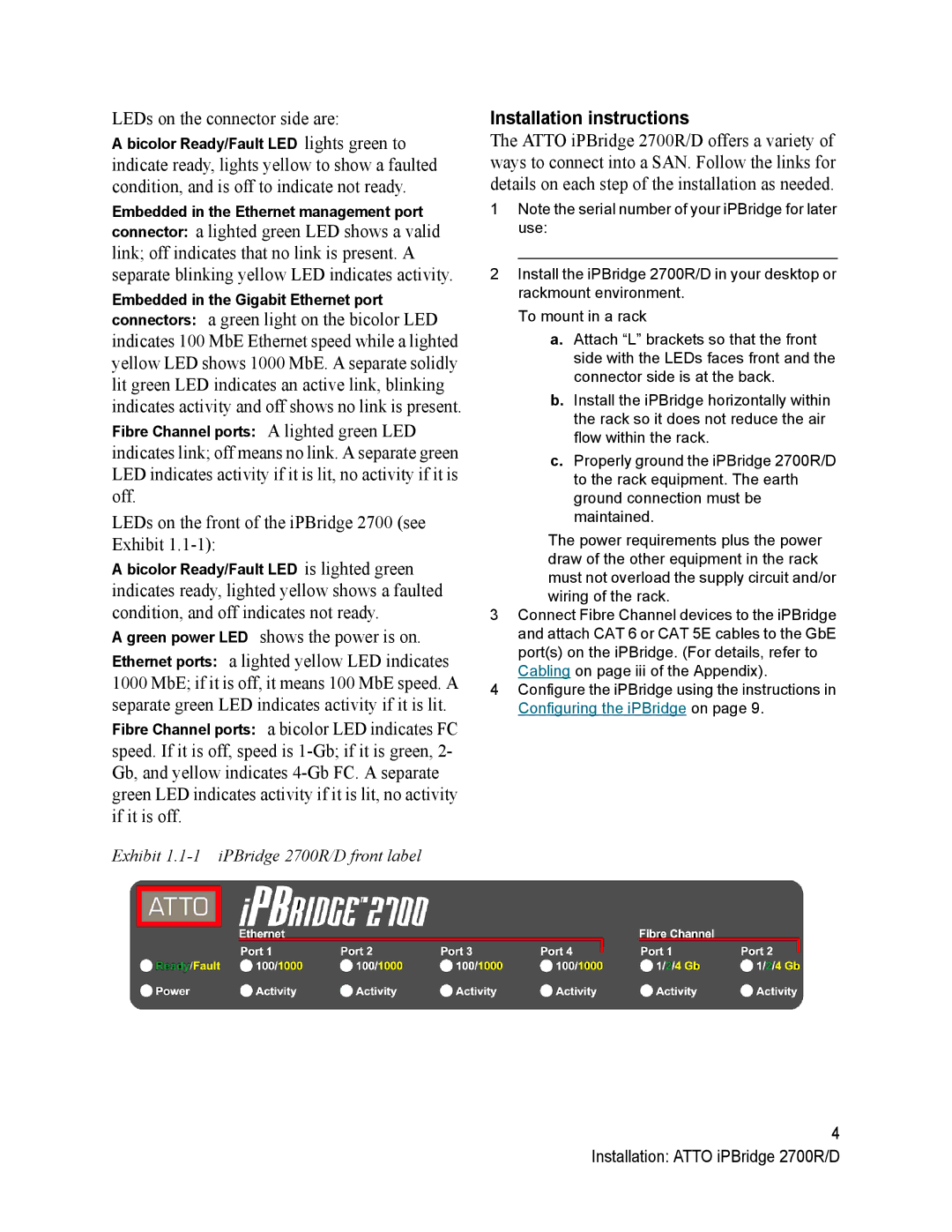
LEDs on the front of the iPBridge 2700 (see Exhibit
A bicolor Ready/Fault LED is lighted green
indicates ready, lighted yellow shows a faulted condition, and off indicates not ready.
A green power LED shows the power is on. Ethernet ports: a lighted yellow LED indicates 1000 MbE; if it is off, it means 100 MbE speed. A separate green LED indicates activity if it is lit. Fibre Channel ports: a bicolor LED indicates FC speed. If it is off, speed is
Exhibit
Installation instructions
The ATTO iPBridge 2700R/D offers a variety of ways to connect into a SAN. Follow the links for details on each step of the installation as needed.
1Note the serial number of your iPBridge for later use:
_____________________________________
2Install the iPBridge 2700R/D in your desktop or rackmount environment.
To mount in a rack
a.Attach “L” brackets so that the front side with the LEDs faces front and the connector side is at the back.
b.Install the iPBridge horizontally within the rack so it does not reduce the air flow within the rack.
c.Properly ground the iPBridge 2700R/D to the rack equipment. The earth ground connection must be maintained.
The power requirements plus the power draw of the other equipment in the rack must not overload the supply circuit and/or wiring of the rack.
3Connect Fibre Channel devices to the iPBridge and attach CAT 6 or CAT 5E cables to the GbE port(s) on the iPBridge. (For details, refer to Cabling on page iii of the Appendix).
4Configure the iPBridge using the instructions in Configuring the iPBridge on page 9.
4 Installation: ATTO iPBridge 2700R/D