Embedded in the Ethernet management port
connector: a lighted green LED shows a valid link; off indicates that no link is present. A separate blinking yellow LED indicates activity.
A bicolor Ready/Fault LED lights green to
indicate ready, lights yellow to show a faulted condition, and is off to indicate not ready.
Installation instructions
1Install the iPBridge 2700C in the target device. (See the board layout diagram below.)
2Connect Fibre Channel devices to the iPBridge and attach CAT 6 or CAT 5E cables to the GbE port(s) on the iPBridge. (For details, refer to Cabling on page iii of the Appendix).
3Configure the iPBridge using the instructions in Configuring the iPBridge on page 9.
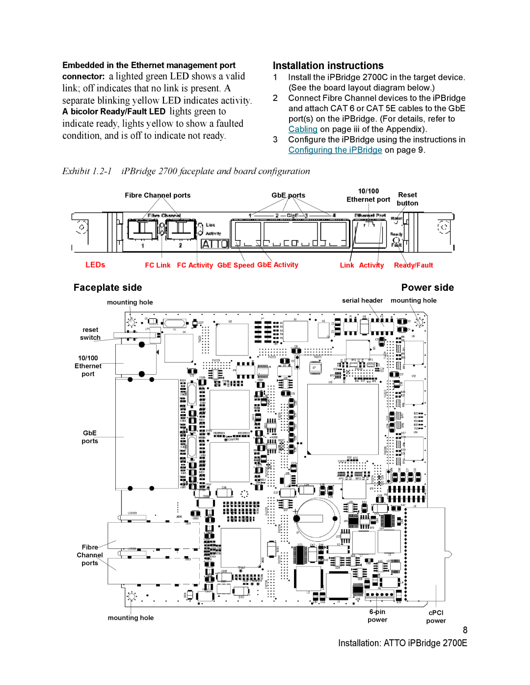
Exhibit
Fibre Channel ports | GbE ports | 10/100 | Reset | |
Ethernet port | ||||
|
| button |
LEDs FC Link FC Activity GbE Speed GbE ActivityLink Activity Ready/Fault
Faceplate side | Power side |
mounting hole | serial header mounting hole |
reset |
|
switch |
|
10/100 |
|
Ethernet |
|
port |
|
GbE ports
Fibre
Channel
ports
mounting hole | cPCI | |
power | power |
8 Installation: ATTO iPBridge 2700E