1.2 ATTO iPBridge 2700C
The ATTO iPBridge 2700C is a
The iPBridge 2700C includes four Ethernet data ports, an Ethernet management port, a serial header and two Fibre Channel ports. It includes a
Dimensions
Width: 6.193 inches
Length: 6.299 inches
Height of tallest component: .545 inches
Environment
Operating Temperature:
Ambient air should not exceed 40°C.
Humidity:
Recommended airflow: 166.25 LFM
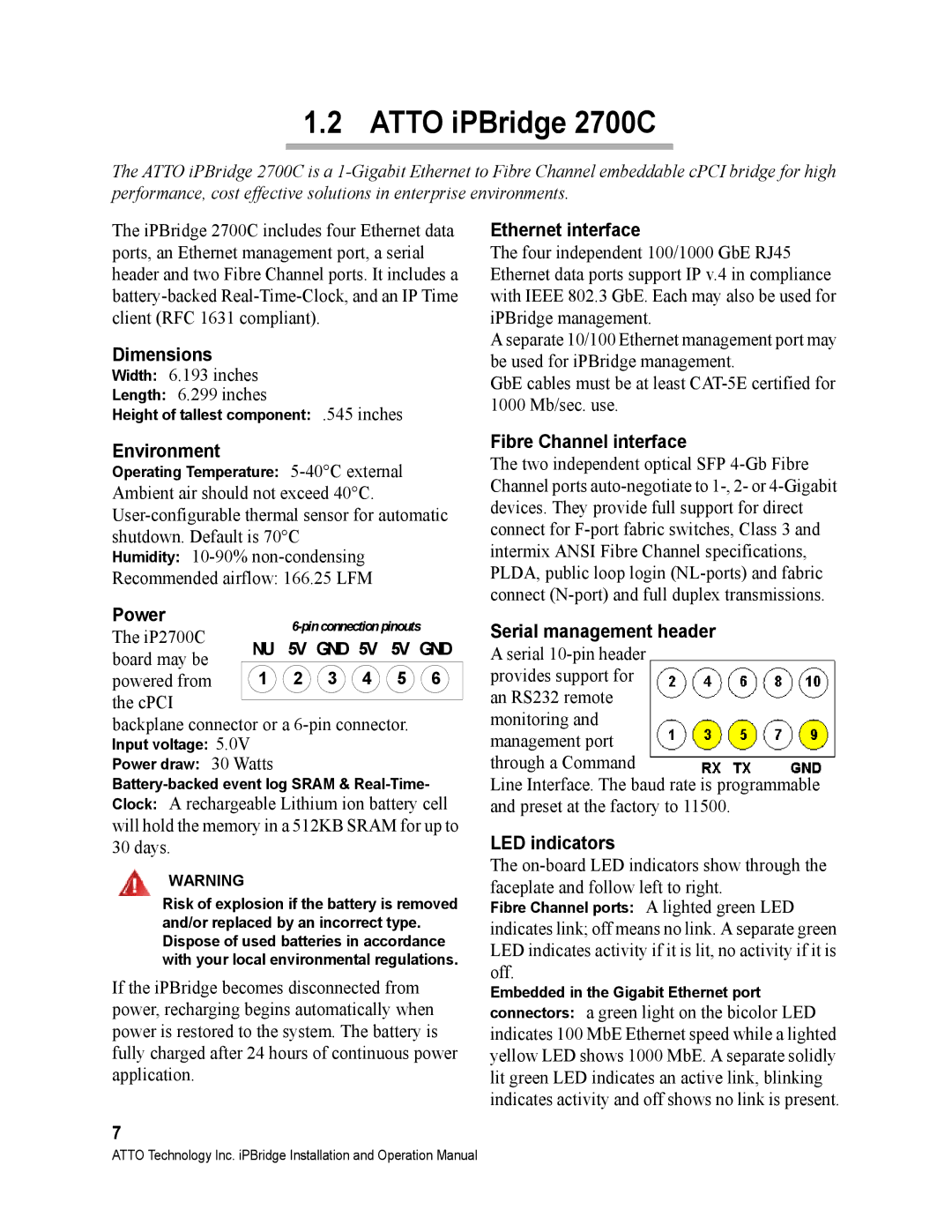
Power |
|
| |||||
The iP2700C |
|
| |||||
NU | 5V GND | 5V | 5V GND | ||||
board may be | |||||||
1 | 2 | 3 | 4 | 5 | 6 | ||
powered from | |||||||
the cPCI |
|
|
|
|
|
| |
backplane connector or a
Input voltage: 5.0V
Power draw: 30 Watts
Clock: A rechargeable Lithium ion battery cell will hold the memory in a 512KB SRAM for up to 30 days.
WARNING
Risk of explosion if the battery is removed and/or replaced by an incorrect type. Dispose of used batteries in accordance with your local environmental regulations.
If the iPBridge becomes disconnected from power, recharging begins automatically when power is restored to the system. The battery is fully charged after 24 hours of continuous power application.
7
Ethernet interface
The four independent 100/1000 GbE RJ45 Ethernet data ports support IP v.4 in compliance with IEEE 802.3 GbE. Each may also be used for iPBridge management.
A separate 10/100 Ethernet management port may be used for iPBridge management.
GbE cables must be at least
Fibre Channel interface
The two independent optical SFP
Serial management header
Aserial
Line Interface. The baud rate is programmable and preset at the factory to 11500.
LED indicators
The
Fibre Channel ports: A lighted green LED
indicates link; off means no link. A separate green LED indicates activity if it is lit, no activity if it is off.
Embedded in the Gigabit Ethernet port
connectors: a green light on the bicolor LED indicates 100 MbE Ethernet speed while a lighted yellow LED shows 1000 MbE. A separate solidly lit green LED indicates an active link, blinking indicates activity and off shows no link is present.
ATTO Technology Inc. iPBridge Installation and Operation Manual