Security Escort Technical Reference Manual 1.0 Security Escor | EN 11 | |
System Architecture | ||
|
Central Console Response |
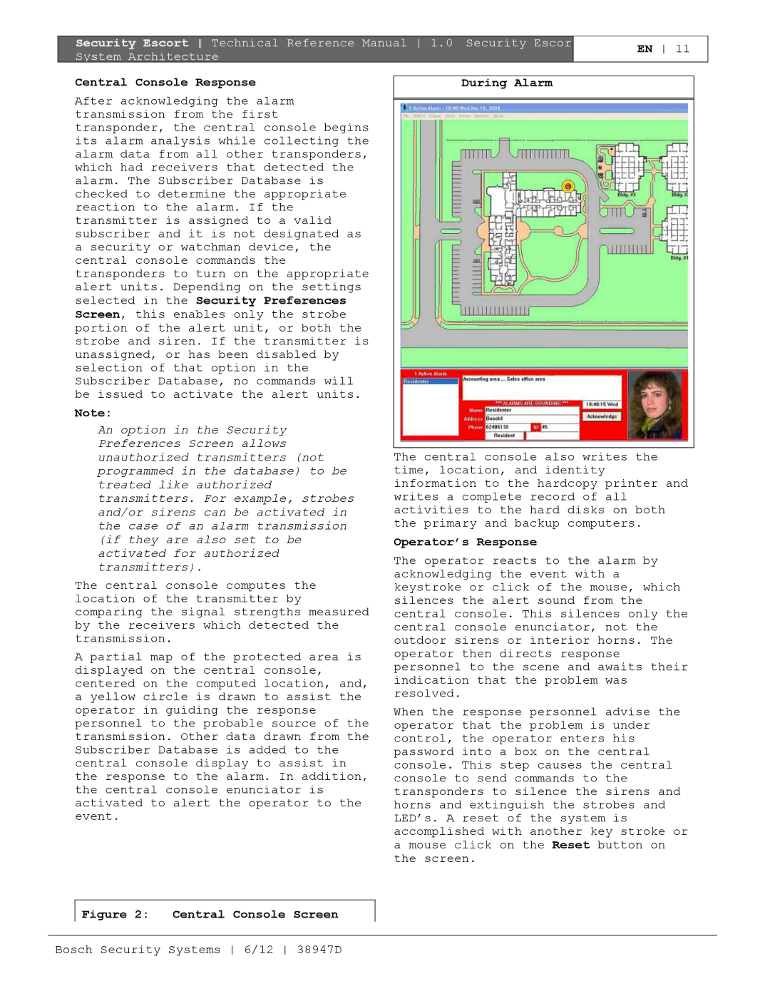
| During Alarm | |
After acknowledging the alarm |
|
| |
|
| ||
transmission from the first |
|
| |
transponder, the central console begins |
|
| |
its alarm analysis while collecting the |
|
| |
alarm data from all other transponders, |
|
| |
which had receivers that detected the |
|
| |
alarm. The Subscriber Database is |
|
| |
checked to determine the appropriate |
|
| |
reaction to the alarm. If the |
|
| |
transmitter is assigned to a valid |
|
| |
subscriber and it is not designated as |
|
| |
a security or watchman device, the |
|
| |
central console commands the |
|
| |
transponders to turn on the appropriate |
|
| |
alert units. Depending on the settings |
|
| |
selected in the Security Preferences |
|
| |
Screen, this enables only the strobe |
|
| |
portion of the alert unit, or both the |
|
| |
strobe and siren. If the transmitter is |
|
| |
unassigned, or has been disabled by |
|
| |
selection of that option in the |
|
| |
Subscriber Database, no commands will |
|
| |
be issued to activate the alert units. |
|
| |
Note: |
|
|
|
An option in the Security |
|
| |
Preferences Screen allows |
|
| |
unauthorized transmitters (not |
| The central console also writes the | |
programmed in the database) to be |
| time, location, and identity | |
treated like authorized |
| information to the hardcopy printer and | |
transmitters. For example, strobes |
| writes a complete record of all | |
and/or sirens can be activated in |
| activities to the hard disks on both | |
the case of an alarm transmission |
| the primary and backup computers. | |
(if they are also set to be |
| Operator’s Response | |
activated for authorized |
| The operator reacts to the alarm by | |
transmitters). |
| ||
| acknowledging the event with a | ||
The central console computes the |
| ||
| keystroke or click of the mouse, which | ||
location of the transmitter by |
| silences the alert sound from the | |
comparing the signal strengths measured |
| central console. This silences only the | |
by the receivers which detected the |
| central console enunciator, not the | |
transmission. |
| outdoor sirens or interior horns. The | |
A partial map of the protected area is |
| operator then directs response | |
| personnel to the scene and awaits their | ||
displayed on the central console, |
| ||
| indication that the problem was | ||
centered on the computed location, and, |
| ||
| resolved. | ||
a yellow circle is drawn to assist the |
| ||
|
| ||
operator in guiding the response |
| When the response personnel advise the | |
personnel to the probable source of the |
| operator that the problem is under | |
transmission. Other data drawn from the |
| control, the operator enters his | |
Subscriber Database is added to the |
| password into a box on the central | |
central console display to assist in |
| console. This step causes the central | |
the response to the alarm. In addition, |
| console to send commands to the | |
the central console enunciator is |
| transponders to silence the sirens and | |
activated to alert the operator to the |
| horns and extinguish the strobes and | |
event. |
|
| LED’s. A reset of the system is |
|
|
| accomplished with another key stroke or |
|
|
| a mouse click on the Reset button on |
|
|
| the screen. |
|
|
|
|
Figure 2: | Central Console Screen |
|
|
Bosch Security Systems 6/12 38947D
