Security Escort Technical Reference Manual 1.0 Security Escor
System Architecture
EN 10
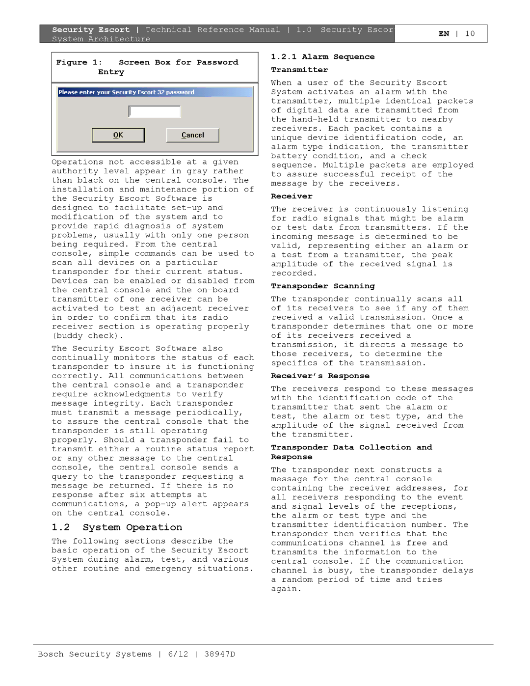
Figure 1: Screen Box for Password Entry
Operations not accessible at a given authority level appear in gray rather than black on the central console. The installation and maintenance portion of the Security Escort Software is designed to facilitate
The Security Escort Software also continually monitors the status of each transponder to insure it is functioning correctly. All communications between the central console and a transponder require acknowledgments to verify message integrity. Each transponder must transmit a message periodically, to assure the central console that the transponder is still operating properly. Should a transponder fail to transmit either a routine status report or any other message to the central console, the central console sends a query to the transponder requesting a message be returned. If there is no response after six attempts at communications, a
1.2System Operation
The following sections describe the basic operation of the Security Escort System during alarm, test, and various other routine and emergency situations.
1.2.1Alarm Sequence Transmitter
When a user of the Security Escort System activates an alarm with the transmitter, multiple identical packets of digital data are transmitted from the
Receiver
The receiver is continuously listening for radio signals that might be alarm or test data from transmitters. If the incoming message is determined to be valid, representing either an alarm or a test from a transmitter, the peak amplitude of the received signal is recorded.
Transponder Scanning
The transponder continually scans all of its receivers to see if any of them received a valid transmission. Once a transponder determines that one or more of its receivers received a transmission, it directs a message to those receivers, to determine the specifics of the transmission.
Receiver’s Response
The receivers respond to these messages with the identification code of the transmitter that sent the alarm or test, the alarm or test type, and the amplitude of the signal received from the transmitter.
Transponder Data Collection and Response
The transponder next constructs a message for the central console containing the receiver addresses, for all receivers responding to the event and signal levels of the receptions, the alarm or test type and the transmitter identification number. The transponder then verifies that the communications channel is free and transmits the information to the central console. If the communication channel is busy, the transponder delays a random period of time and tries again.
Bosch Security Systems 6/12 38947D