Security Escort Technical Reference Manual 2.0 Setting Up The System
EN 13
2.0Setting Up The System
2.1Initial System Configuration
The default password is PPP. The default password, the Master password, and passwords for all system operators added by referring to the Operators Database in the Security Escort Operations Manual should be changed.
∙To generate the map file for the screen display, refer to Section 5.1 Map File Generation and Scaling.
∙To setup the transponder COMM ports refer to the Section 3.3.18 Transponder Comm Port Setup Screen.
∙To setup the system COMM ports refer to the Section 3.3.19 Remote Comm Port Setup Screen.
∙To set the function of the system COMM ports and setup remote access, see Section 3.3.20 Remote Setup Screen.
∙To program the system configuration, see Section 3.1.6 Transponder Database.
∙To program the system responses to an alarm, see Section 3.2.3 Security Preferences Screen.
∙To program the system responses to troubles, see Section 3.3.3 Popup Trouble Filter.
∙After communications to the transponders are established for any transponder that uses a Proxim Radio to communicate, program the Uses Proxim Radio field in the Transponder Parameter Change Screen. If all alarms are to be silent, program the Run Silent field. (See Section 3.3.11 Transponder Parameter Change Screen.)
∙If this system has master and slave computers, set the Default Master Computer and Default Slave Computer. (See Section 3.3.20 Remote Setup Screen.)
∙If using pager access in this system, see Section 3.3.23 Pager Setup Screen.
∙If this computer runs other programs at the same time, Security Escort is running, set the Not Always Top Window field (see Section 3.2.3 Security Preferences Screen).
∙To program the ID Receiver to automatically enter the transmitter IDs, see Section 3.2.3 Security Preferences Screen.
∙To set the names of the subscriber classes, see System Default Screen in the Security Escort Operations Manual.
∙To program the transmitters into the Subscriber Database, refer to the Security Escort Operations Manual.
3.0System Menus and Screens
3.1File Menu
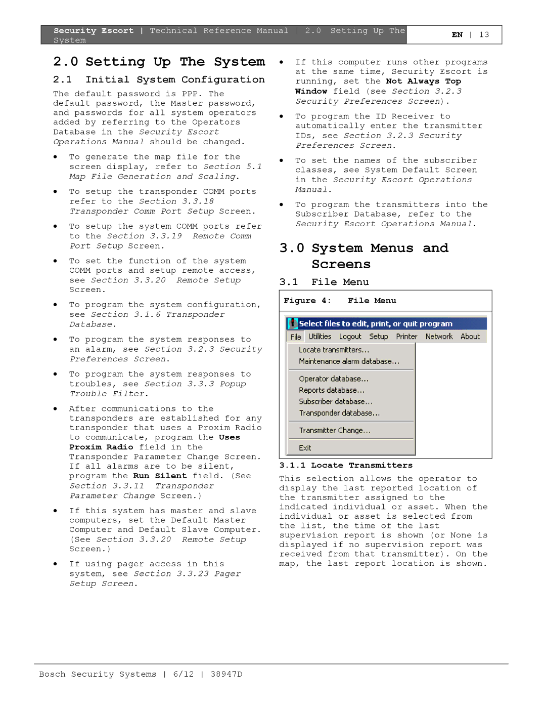
Figure 4: File Menu
3.1.1 Locate Transmitters
This selection allows the operator to display the last reported location of the transmitter assigned to the indicated individual or asset. When the individual or asset is selected from the list, the time of the last supervision report is shown (or None is displayed if no supervision report was received from that transmitter). On the map, the last report location is shown.
Bosch Security Systems 6/12 38947D