Security Escort
Limited Warranty
Software License Agreement
You MAY
You may not
Remedy
Table of Contents
Figures
Tables
Subscriber Database Advanced
Security Escort System Architecture
System Components
Maintenance Transmitter
Point Transmitter
Receiver
Alert Unit
Software Overview
Transponder
Central Console
Alarm Sequence Transmitter
System Operation
Transponder Scanning
Receiver’s Response
Central Console Response During Alarm
Selected in the Security Preferences
Operator’s Response
Central Console Screen
Central Console Response
Multiple Alarms
Test Sequence Transmitter
Setting Up The System
Initial System Configuration
System Menus and Screens
File Menu
Reports Database
Subscriber Database
Pager Password
Phone Number
Pager ID
Pager Group
Enable Reed Switch
Disable Shorted Loop
Alarm on Shorted Loop
Alarm When Armed, Trouble When Disarmed on Shorted Loop
Alarm Group
Transponder Area
Requires Check-in
Done
Database Record
Created, Modified, Modify Oper
Transponder ID
Comm Port Index
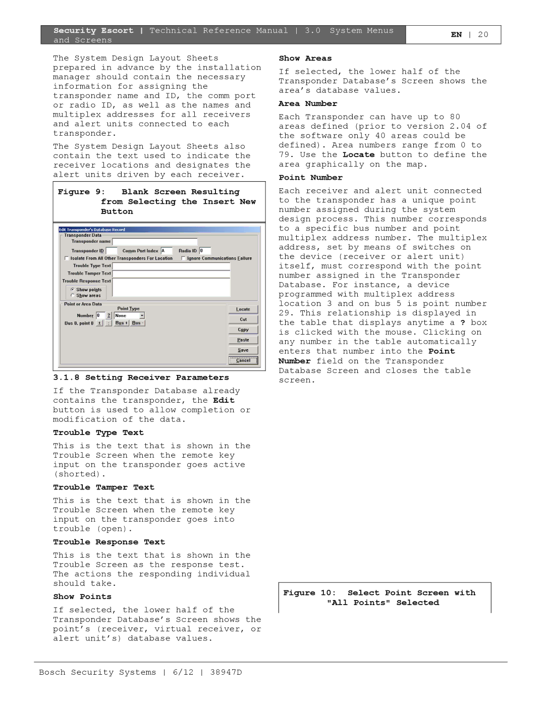
Insert New
Edit Data
Kill Transponder
Delete Point
Trouble Type Text
Trouble Tamper Text
Trouble Response Text
Show Points
+, -, Bus + and Bus
Point Type
Data Entry After Selection of Receiver Point Type
If the Enable algorithm tweaks field is
Alert 1, Alert 2, Alert 3, and Test Selection
Assigning Alert Units to Receivers
Algorithm
Video Switcher
Location
Map
Floor
Cancel
Virtual Fence Area
Cut
Paste
Utilities Menu
Backup
Restore Screen
Floppy a
Clear Entire File
Turn On Alarm Strobes
Display Unauthorized Alarms
Sound Unauthorized Alarms
Turn On Outside Sounders
Limit Alarms to 1 Transponder
Require Alarm Report
Security Alarms Silent
Installer Alarms Silent
Auto Silence Alarm In X Seconds
Man Down Delay Timer X Seconds
Man down jitter timer ‘X’ Seconds
Auto Reset Comm Ports ‘X’ Hours
Pop-up Trouble Box Contact Information
System Defaults Screen
Guard Tour Minutes
Low Battery Report
Not Testing Report
New Alarm Reports
Weekly Maintenance Test Report
View Alarm Groups
Schedules Screen
This schedule defines the check-in times
Edit Schedule Times
View Alarm Groups Screen
Ellipsis …
Remove
Add
Alarm Groups Screen
Alarm Group #
Alarm Group State Screen
On armed
Setup Menu
History Filter Screen
Printer
History Archive File a
History Archive File B
Points, Reporting Alarm
Transmitter Low Battery
Database Backup and Restore
Database Errors
Login Changes
Analyze Alarms
Master Computer Switch
Point Troubles
Low Battery
Transponder Troubles Popup
Pager
AC Loss
Bus Faults
Output Device Error
Tamper
Remote Key Activation
Pop-up Trouble and Pager Delay
Map Commands
Communications Port Monitor Comm Port Overload
Network Comm Failure
Device Type Map
Not Responding Map
Received Transmission Map
Strobe Red LED Map
Low Battery Map
Out Of Service Map
Point Out Of Service
Point In Service
On Output Command
Click On Output Command again Transponder
Total Alarms Received
Using Reset Transponder Troubles
Incoming Format Errors
Successful Incoming Messages
Incoming Retried Messages
Total Outgoing Messages
Enable Remote Key
Tamper Map
AC Loss Map
Refresh Data
Alarm Min Level
Alarm Differential
Test Differential
Byte
RAM EE Buss Fault
Receiver Configuration Screen
RAM Point Info
RAM Point Stat
Abort Button to Remove a Device from the Setup Mode
Reset Point
Red LED Strobe
Off
Ambient
Enable Rec
Stop Test and Reset Counters
Incoming Communication Errors
Transmitting Point
Total Remote Access Connections
Total Wrong Access Code Attempts
Last Remote Access Time
Reset Status
Maximum Low Battery Messages
Maximum Test Strobe Messages
Max Man Down Messages
Supervision Monitors
Show Maintenance Levels
Enable Algorithm Tweaks
Display Maintenance Alarm
Sound Maintenance Alarm
No Password Timeout
Bring to Front on Alarm
Alarm Zone
Bring to Front on Trouble
Alarm Spot Size
Transponder Comm Port Setup Screen
Linear Depth
Low Depth
Mon Power
Remote Comm Port Setup Screen
Carrier Det
No CTS
Remote Setup Screen
Default Slave Computer
Password
LF Only
Password Verify
Disabled
Video Switcher Control
Video Switcher Restore
Security Escort System used for remote access
Edit
Delete
Dial
Access Password
Verify Password
Entered into Access Password Character System ID
Pager Setup Screen
Printer Menu
Select Alarm Printer Screen
Hold Printer Data
Select
Formfeed
Network Menu
Common Open File Screen
Bosch Security Systems 6/12 38947D
Subscriber Image File Path
Subscriber Image Extension
Subscriber Image Scaling %
Network Socket Status Screen
Winsock Data Screen
Demo Lanyard Alarm, Subscriber
About Menu
Demo Man Down Alarm, Subscriber
Demo Test Subscriber 3 with low battery
Demo Maintenance Alarm
Demo Maintenance Test
Files Required For Security Escort
Image Files
Map File Generation Scaling
Subscriber Images
Security Escort Pager Setup
Multiple Map Files
Dial-up Paging Modem Setup
Local Paging Setup
Service and Security Alarm Pager Setup
Subscriber Database Advanced Screen
Alarm Area Setup
Manual Pages
Importing a Subscriber Database
Importing a Subscriber Database
Data Fields Excel Restrictions Required Order Column
Bosch Security Systems 6/12 38947D
Autobackup to the slave database
CR/LF
Idle Time
Multiplex Point
Refresh Data 47, 53, 54
System Preferences
Security Escort Technical Reference Manual Index
Bosch Security Systems 38947D