Security Escort Technical Reference Manual 6.0 Security Escor
Pager Setup
EN 73
∙Up to 256 individual alphanumeric pagers; grouped into 99 groups of eight.
∙Both dial up and local serial port connected paging systems, in the same system, at the same time.
∙Service pages that can activate a group of eight service pagers in addition to a single pager.
∙Alarm pages that can activate a group of eight alarm pagers in addition to a single pager. All alarms located in an alarm area can page an additional group of eight pagers specific to that area.
∙Manual pages sent to any individual pager or pager group.
∙All paging system communication using the TAP or PET protocols. This is true for both the
The system does not support numeric only or vibrate only pagers.
At this time, the only local paging system tested is TEKK model:
Set the DIP switch for TAP Mode, 9600N81, Switch 6 off, all other switches on.
The pager ID to be used for each pager is the
Message Encoding Type (E) must be a “1” for alphanumeric coding.
RF data rate (R) is “5” for 512 BPS, “1” for 1200 BPS, or “2” for 2400 BPS. Many systems use 512 BPS for more reliable transmissions.
Function Code (F) may be set to one through four for a specific function code or zero for the default (recommend the Function Code be set to zero).
For an alphanumeric pager communicating at 512 BPS, the pager ID in our example is 0991001150.
For
Service pages page the members of the service group first, followed by the single service pager.
Alarm pages page the members of the alarm area paging group first (if any), followed by the alarm group, and finally the single alarm pager.
6.1Dial-up Paging Modem Setup
All
6.2Local Paging Setup
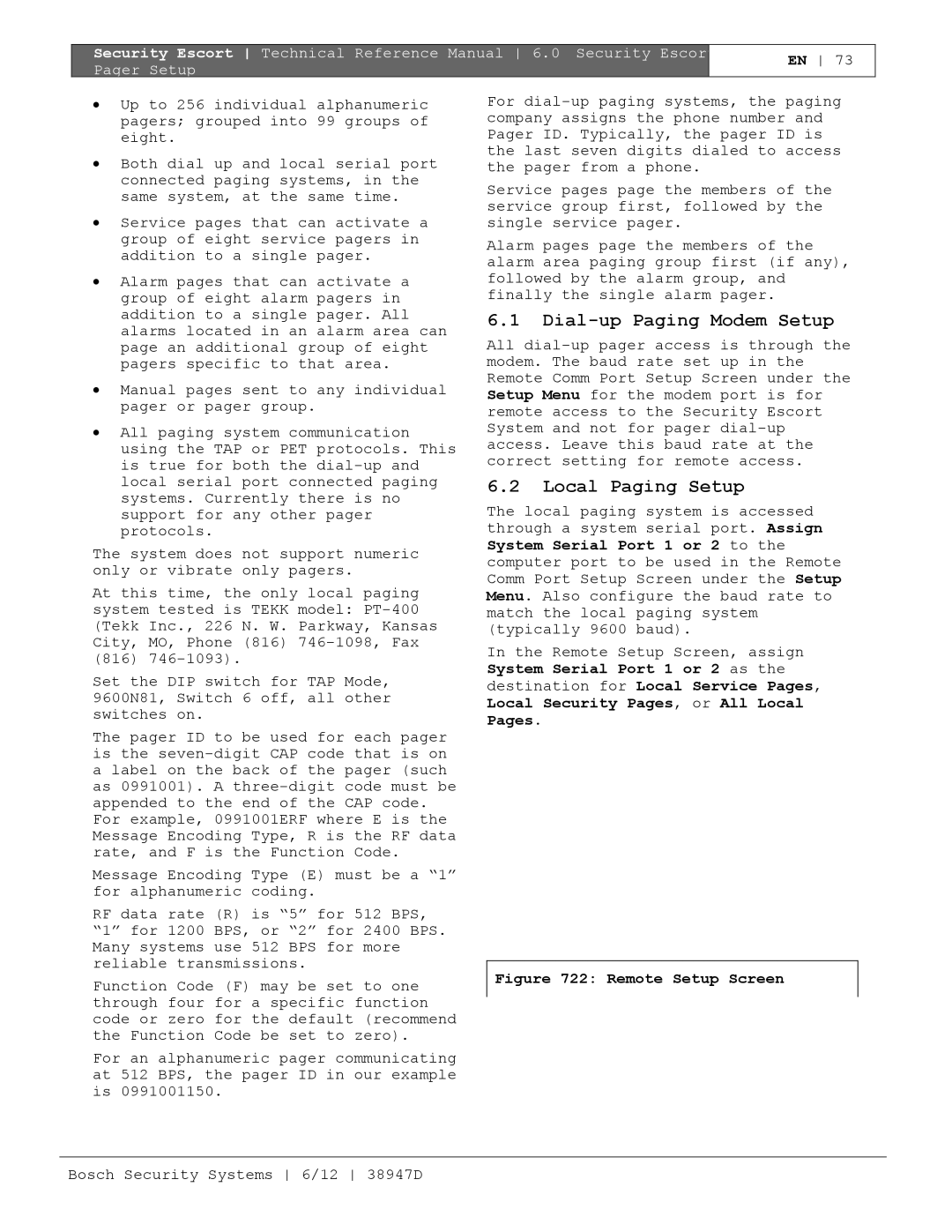
The local paging system is accessed through a system serial port. Assign System Serial Port 1 or 2 to the computer port to be used in the Remote Comm Port Setup Screen under the Setup Menu. Also configure the baud rate to match the local paging system (typically 9600 baud).
In the Remote Setup Screen, assign System Serial Port 1 or 2 as the destination for Local Service Pages, Local Security Pages, or All Local Pages.