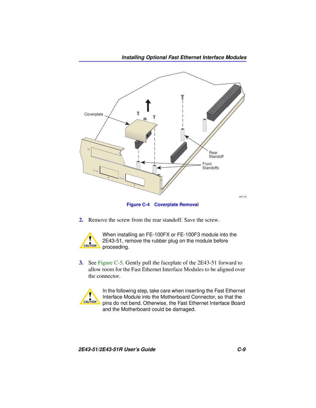
Installing Optional Fast Ethernet Interface Modules
Coverplate
Rear
Standoff
![]() Front
Front
![]() Standoffs
Standoffs
Figure C-4 Coverplate Removal
2.Remove the screw from the rear standoff. Save the screw.
When installing an
!
3.See Figure
In the following step, take care when inserting the Fast Ethernet
!Interface Module into the Motherboard Connector, so that the
CAUTION | pins do not bend. Otherwise, the Fast Ethernet Interface Board |
| |
| and the Motherboard could be damaged. |
|