Chapter 3: Installation
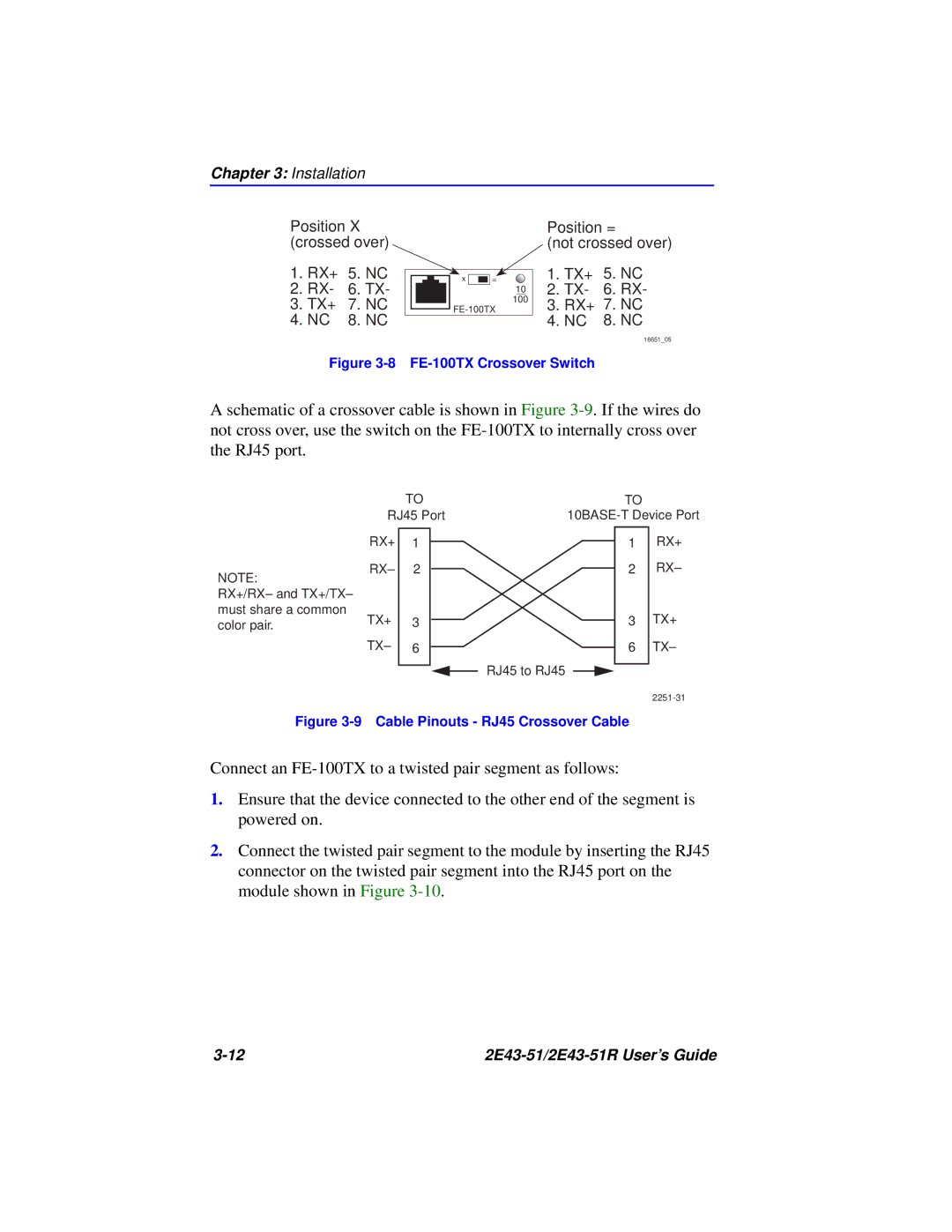
Position X (crossed over)
1.RX+ 5. NC
2.RX- 6. TX-
3.TX+ 7. NC
4.NC 8. NC
x |
|
|
| = |
|
|
|
|
|
10
100
Position =
(not crossed over)
1.TX+ 5. NC
2.TX- 6. RX-
3.RX+ 7. NC
4.NC 8. NC
16651_05
Figure 3-8 FE-100TX Crossover Switch
A schematic of a crossover cable is shown in Figure
NOTE:
RX+/RX– and TX+/TX– must share a common color pair.
| TO |
|
|
|
|
| TO |
| ||
RJ45 Port |
| |||||||||
RX+ |
|
|
|
|
|
|
|
|
| RX+ |
1 |
|
|
|
|
|
|
| 1 | ||
RX– | 2 |
|
|
|
|
|
|
| 2 | RX– |
TX+ | 3 |
|
|
|
|
|
|
| 3 | TX+ |
|
|
|
|
|
|
| ||||
|
|
|
|
|
|
| ||||
TX– | 6 |
|
|
|
|
|
|
| 6 | TX– |
|
|
|
|
| RJ45 to RJ45 |
|
|
|
| |
|
|
|
|
|
| |||||
|
|
|
|
|
|
|
| |||
Figure 3-9 Cable Pinouts - RJ45 Crossover Cable
Connect an
1.Ensure that the device connected to the other end of the segment is powered on.
2.Connect the twisted pair segment to the module by inserting the RJ45 connector on the twisted pair segment into the RJ45 port on the module shown in Figure
|