ATM Configuration
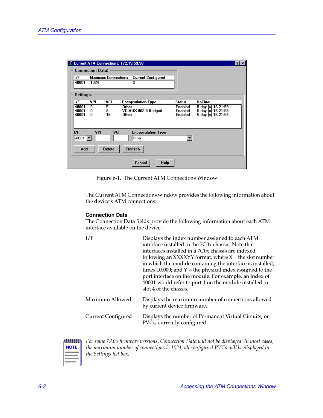
Figure 6-1. The Current ATM Connections Window
The Current ATM Connections window provides the following information about the deviceÕs ATM connections:
Connection Data
The Connection Data Þelds provide the following information about each ATM interface available on the device:
I/F | Displays the index number assigned to each ATM |
| interface installed in the 7C0x chassis. Note that |
| interfaces installed in a 7C0x chassis are indexed |
| following an XXXXYY format, where X = the slot number |
| in which the module containing the interface is installed, |
| times 10,000; and Y = the physical index assigned to the |
| port interface on the module. For example, an index of |
| 40001 would refer to port 1 on the module installed in |
| slot 4 of the chassis. |
Maximum Allowed | Displays the maximum number of connections allowed |
| by current device Þrmware. |
Current ConÞgured | Displays the number of Permanent Virtual Circuits, or |
| PVCs, currently conÞgured. |
NOTE |
For some 7A06 Þrmware versions, Connection Data will not be displayed. In most cases, the maximum number of connections is 1024; all conÞgured PVCs will be displayed in the Settings list box.
Accessing the ATM Connections Window |