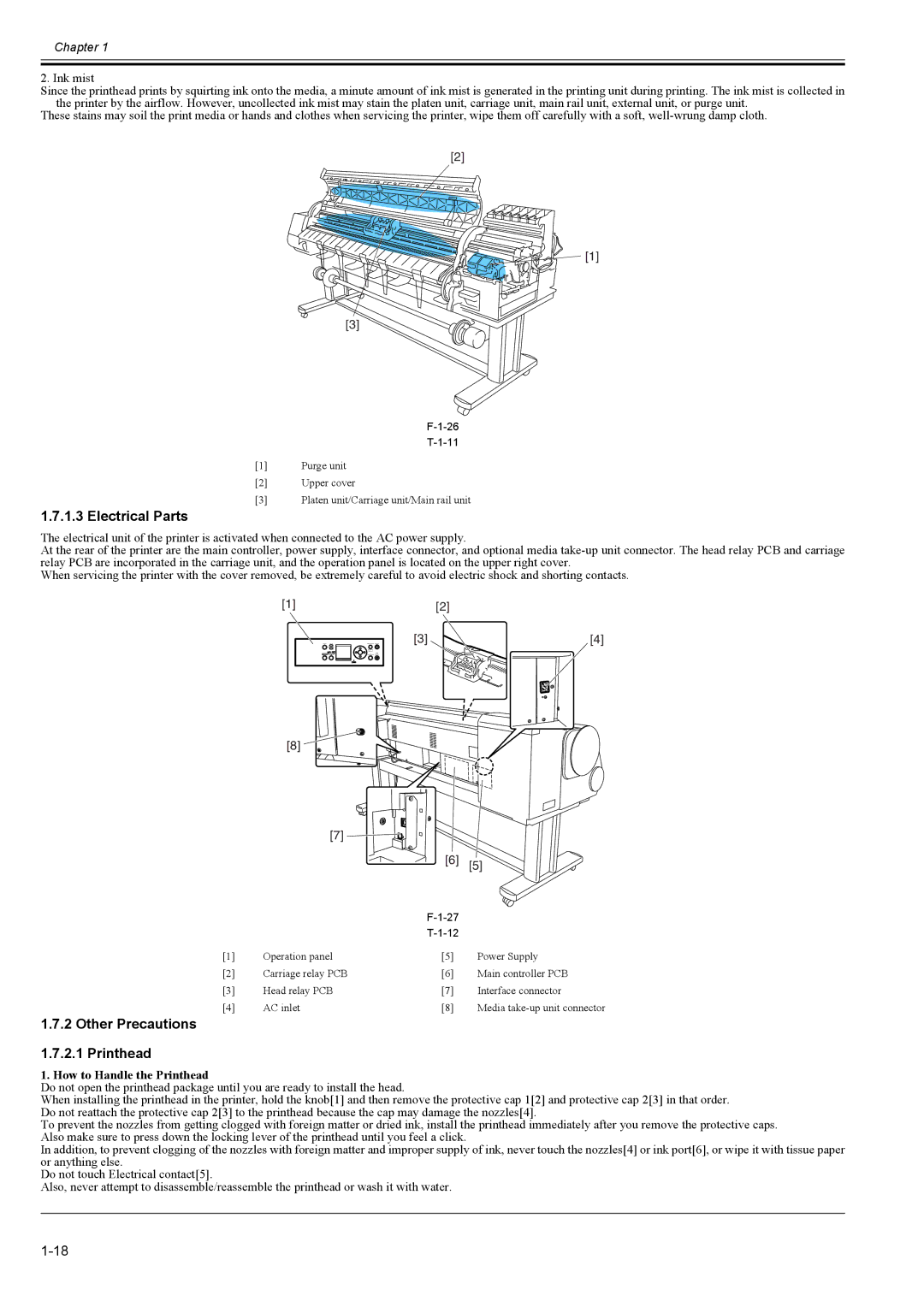
Main
Page
Page
Symbols Used
Symbol Description
Page
Page
Page
Page
Page
Page
Page
Page
Page
Page
Page
Page
1-1
1.1 Product Overview
1.1.1 Product Overview
1.2 Features
1.2.1 Features
1.2.2 Printhead
1-2
1.2.3 Ink tank
1.2.4 Cutter unit
1.2.5 Roll holder
1.2.6 Media take-up unit (option)
1.3 Product Specifications
1.3.1 General Specifications
1-4
1-5
1.4 Detailed Specifications
1.4.1 Printing mode
1.4.2 Interface Specifications
1-6
1.5 Names and Functions of Components
1.5.1 Front
1-7
1.5.2 Rear
1.5.3 Carriage
Chapter 1
1-8
1.6 Basic Operation
1.6.1 Operation panel
[1]
[4] [5]
[9] [10]
1-9
1.6.2 Main menu
1-10
1-11
1-12
1-13
1-14
1-15
Meaning of code address
Chapter 1
1-16
1.7 Safety and Precautions
1.7.1 Safety Precautions 1.7.1.1 Moving Parts
1-17
1.7.1.2 Adhesion of Ink
1-18
1.7.1.3 Electrical Parts
1.7.2 Other Precautions 1.7.2.1 Printhead
1-19
1.7.2.2 Ink tank
1-20
1.7.2.3 Handling the Printer
1-21
1.7.3 Precautions When Servicing Printer 1.7.3.1 Notes on the Data Stored in the Printer
1.7.3.2 Confirming the Firmware Version
1.7.3.3 Precautions Against Static Electricity
1.7.3.4 Precautions for Disassembly/Reassembly
Page
Page
Page
Page
Page
2-1
2.1 Basic Operation Outline
2.1.1 Printer Diagram
2.1.2 Print Driving
2.2 Firmware
2.2.1 Operation Sequence at Power-on
2-2
2.2.2 Operation Sequence at Power-off
2-3
2.2.3 Print Control
2-4
2.2.4 Print Position Adjustment Function
2.2.5 Head Management
2.2.6 Printhead Overheating Protection Control
2.2.7 Pause between Pages
2.3 Printer Mechanical System
2-6
2.3.2.2 Ink Tank Unit
2-7
2-8
2.3.2.3 Carriage Unit
2-9
2-10
2.3.2.4 Printhead
2-11
2.3.2.5 Purge Unit
Resin Sillicon plate Heater Shared ink chamber
Heater
Chapter 2
2-12
The cleaning operation is executed at the following timing.
2-13
2-14
2.3.2.6 Maintenance Cartridge
2.3.2.7 Air Flow
2.3.3 Paper Path 2.3.3.1 Outline
2-15
2-16
2.3.3.2 Paper Path
2.3.3.3 Cutter Unit
2.4 Printer Electrical System
2.4.1 Outline 2.4.1.1 Overview
Chapter 2
2-17
F-2-17
IC1
IC3900
IC2802
2-18
2-19
2.4.3 Carriage Relay PCB 2.4.3.1 Carriage relay PCB components
2.4.4 Head Relay PCB 2.4.4.1 Head relay PCB components
2.4.5 Motor Driver 2.4.5.1 Media take-up unit components
2-20
2.5 Detection Functions with Sensors
2.5.1 Cover system
2-21
2.5.2 Ink passage system
2-22
2-23
2.5.3 Carriage system
Printhead Nozzle unit
Head management sensor unit
2-24
2.5.4 Paper path system
2.5.5 Humidity sensor
2-25
2.5.6 Media take-up Unit
Page
Page
Page
Page
Page
3-1
3.1 Installation
3.1.1 Making Pre-Checks 3.1.1.1 Making Pre-Checks
3.1.2 Unpacking and Installation 3.1.2.1 Checking the Contents
Chapter 3
3-2
b) Stand and basket
3-3
3.1.2.2 Assembling the Stand
3-4
3-5
Page
3-7
3.1.2.4 Installing the Basket
3-8
Page
Page
Page
Page
Page
3-14
3-15
3-16
Page
3-18
Page
Page
Page
Page
Page
Page
4-1
4.1 Service Parts
4.1.1 Service parts
4.2 Disassembly/Reassembly
4.2.1 Diassembly/Reassembly
4-2
4-3
4-4
4.3 Points to Note on Disassembly and Reassembly
4.3.1 Note on locations prohibited from disassembly
4.3.2 Moving the carriage manually
4-5
4.3.3 Units requiring draining of ink
4.3.4 External covers
4-6
4-7
4-8
[2]
4-9
4-10
4-11
4.3.5 Drive unit
4-12
4.3.6 Carriage unit
4-13
4-14
4-15
4-16
4.3.7 Ink tube unit
4-17
4.3.8 Feeder unit
4.3.9 Purge unit
4-18
4.3.10 Ink tank unit
4-19
4-20
4-21
4.3.11 Linear encoder
4-22
4.3.12 Head management sensor
4.3.13 PCBs
4-23
4.3.14 Opening the cap and moving the wiper unit
4.3.15 Opening and closing ink supply valves
4-24
4.3.16 Draining the ink
4-25
4.4 Applying the Grease
4.4.1 Applying the Grease
4-26
4-27
4.5 Adjustment and Setup Items
4.5.1 Action to take after replacing the feed roller HP sensor, feed roller encoder, or feed roller
4.5.2 Action to take after replacing the carriage unit or multi sensor
4.5.3 Action to take after replacing the head management sensor
Page
Page
Page
Page
Page
Chapter 5
5-1
5.1 Periodic Replacement Parts
5.1.1 Periodic replacement parts
5.2 Consumable Parts
5.2.1 Consumable parts
5.3 Periodic Maintenance
Page
Page
Page
Page
Page
6-1
6.1 Troubleshooting
6.1.1 Outline 6.1.1.1 Outline of Troubleshooting
6.1.2 Troubleshooting When Warnings Occur 6.1.2.1 Ink Level: Check
6.1.2.2 Check maint cartridge capacity.
6.1.2.3 Ink tank is empty. Replace the ink tank.
6-2
6.1.2.6 End of paper feed. Cannot feed paper more.
6.1.2.7 Paper Type Wrong
6.1.2.8 GARO W12xx
6.1.2.9 Check printed document.
6-3
6.1.2.11 Parts replacement time has passed. Call for service.
6.1.3 Troubleshooting When Errors Occur 6.1.3.1 03870001-2015 Cutter error
6.1.3.3 03031000-2E0F Upper cover sensor error
6.1.3.4 03031101-2E10 Ink tank cover switch error
6-4
6.1.3.5 03031000-2E11 Carriage cover sensor error
6.1.3.6 03031000-2E12 Defective paper release lever
6.1.3.7 03010000-2016/03010000-2E27 Paper feed error
6.1.3.8 03010000-200D Cut media end error
6-5
6.1.3.10 03862000-2E09 Insufficient roll media error
6.1.3.11 03890000-2920 Media take-up motor error
6.1.3.12 03890000-2921 Media take-up paper detection sensor error
6.1.3.13 03060A00-2E1B Roll media end error
6-6
6.1.3.14 03861001-2405/03861001-2406 Borderless printing error
6-7
6.1.3.23 03800101-2800/03800102-2808/03800201-2804/03800202-2807 Printhead installing error
6-8
6.1.3.24 03800501-280D/03800502-280E Defective printhead nozzle
6.1.3.27 03130031-260E Gap detection error
6.1.3.28 03130031-260F Gap adjustment error
6-9
6.1.3.29 03130031-2618 VH voltage abnormality error
6.1.3.30 03800500-2F2F/03800500-2F30 Head management sensor error
6.1.3.31 03130031-2F16 Mist fan error
6.1.3.32 03130031-2F17 Suction fan error
6-10
6.1.3.34 03130031-2F25 Carriage home position error
6.1.3.35 03130031-2F26/03130031-2F27 Carriage motor error
6.1.3.36 03130031-2F1F/03130031-2F20 Defective sensor in purge unit
6.1.3.37 03130031-2F22/03130031-2F23/03130031-2F2D Purge motor driving error
6-11
6.1.3.40 03130031-2F2E Roll media feeding error
6.1.3.41 03130031-2F28 Lift motor time out error
6.1.3.42 03130031-2F13 A/D Converter external trigger output stopped
6.1.3.43 03130031-2F14 ASIC Register cannot be written.
6-12
6.1.4 Troubleshooting When Service Call Errors Occur 6.1.4.1 E141-4046 Recovery system's count error
6.1.4.2 E144-4047 Supply system's count error
6.1.4.3 E146-4001 Waste ink count full
6.1.4.4 E161-403E/E161-403F Abnormally high head temperature
6.2 Location of Connectors and Pin Arrangement
6.2.1 Main controller PCB
6-14
6-15
6-16
6-17
6-18
6-19
6-20
6-21
6-22
6.2.2 Carriage relay PCB
6-23
6-24
6-25
6-26
6-27
6-28
6-29
6-30
6.2.3 Head relay PCB
6-31
6-32
6-33
6-34
6-35
6-36
6-37
6.3 Version Up
6.3.1 Firmware Update Tool
6-38
6.4 Service Tools
6.4.1 List of Tools
Page
Page
Page
Page
7-1
7.1 Service Mode
7.1.1 Service Mode
7.1.2 Map of the Service mode
Test Print
System Setup
7-2
7-3
7-4
7-5
Chapter 7
7-6
7.1.3 Details for Service mode
3) HEAD Displays the following EEPROM information of the printhead.
4) INK Displays the numbers of days passed since installation of the following ink tanks.
7-7
Chapter 7
7-8
2) CARRIAGE: Counters related to carriage unit
3) PURGE: Counters related to purge unit
4) CLEAR: Counters related to counter initialization
5) EXCHANGE: Counters related to parts replacement
7-9
6) DETAIL-CNT: Other counters
7) INK-USE1: Counters related to ink consumption
8) INK-USE2: Counters related to ink consumption
9) INK-EXC: Counters related to ink tank replacement
7-10
12) MEDIASIZE1 ROLL: Counters related to roll media printing
17) HEAD DOT CNT.2: Counter related to dot count
13) MEDIASIZE2 ROLL: Counters related to roll media printing
14) MEDIASIZE1 CUT: Counters related to cut sheet printing
7-11
18) PARTS CNT. : Counter related to consumable parts
7-12
7.2 Special Mode
7.2.1 Special Modes for Servicing
Page
Page
Page
Page
8-1
8.1 Outline
8.1.1 Outline
8.2 Warning Table
8.2.1 Warnings
Chapter 8
8.3 Error Table
8.3.1 Errors
The codes correspond to the numbers shown on the DISPLAY in the service mode.
8-3
8-4
8-5
8.4 Sevice Call Table
8.4.1 Service call errors
Codes correspond to the numbers shown on the DIPLAY in the service mode.