(see wiring diagrams or certified drawings). The temperature sensor must be wired to terminal J4-13 and J4-14. To configure Reset Type 2, enter the temperature of the remote sensor at the point where no temperature reset will occur (REMOTE TEMP –> NO RESET). Next, enter the temperature at which the full amount of reset will occur (REMOTE TEMP –> FULL RESET). Then, enter the maximum amount of reset required to operate the chiller (DEGREES RESET). Reset Type 2 can now be activated.

RESET TYPE 3 — Reset Type 3 is an automatic chilled water temperature reset based on cooler temperature difference. Reset Type 3 adds ± 30° F (± 16° C) based on the temperature difference between the entering and leaving chilled water temperature.

To configure Reset Type 3, enter the chilled water tempera- ture difference (the difference between entering and leaving chilled water) at which no temperature reset occurs (CHW DELTA T –> NO RESET). This chilled water temperature dif- ference is usually the full design load temperature difference. Next, enter the difference in chilled water temperature at which the full amount of reset occurs (CHW DELTA T –> FULL RE- SET). Finally, enter the amount of reset (DEGREES RESET). Reset Type 3 can now be activated.

Demand Limit Control Option — The demand limit control option (20 mA DEMAND LIMIT OPT) is externally controlled by a 4 to 20 mA or 1 to 5 vdc signal from an energy management system (EMS). The option is set up on the RAMP_DEM screen. When enabled, 4 mA is the 100% de- mand set point with an operator-configured minimum demand at a 20 mA set point (DEMAND LIMIT AT 20 mA).

The auto. demand limit is hardwired to terminals J5-1 (–) and J5-2 (+) on the CCM. Switch setting number 1 on SW2 will determine the type of input signal. With the switch set at the ON position the input is configured for an externally pow- ered 4 to 20 mA signal. With the switch in the OFF position the input is configured for an external 1 to 5 vdc signal.

Surge Prevention Algorithm (Fixed Speed Chiller) — This is an operator-configurable feature that can determine if lift conditions are too high for the compressor and then take corrective action. Lift is defined as the difference be- tween the pressure at the impeller eye and at the impeller discharge. The maximum lift a particular impeller wheel can perform varies with the gas flow across the impeller and the size of the wheel.

A surge condition occurs when the lift becomes so high the gas flow across the impeller reverses. This condition can even- tually cause chiller damage. The surge prevention algorithm notifies the operator that chiller operating conditions are mar- ginal and to take action to help prevent chiller damage such as lowering entering condenser water temperature.

The surge prevention algorithm first determines if correc- tive action is necessary. The algorithm checks 2 sets of opera- tor-configured data points, the minimum load points (MIN. LOAD POINT [T1,P1]) and the full load points (FULL LOAD POINT [T2,P2]). These points have default settings as defined on the OPTIONS screen or on Table 4.

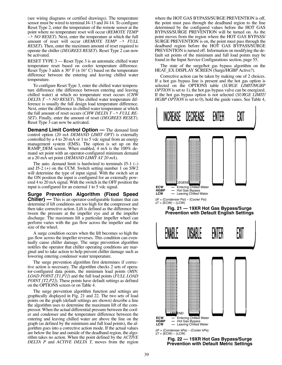
The surge prevention algorithm function and settings are graphically displayed in Fig. 21 and 22. The two sets of load points on the graph (default settings are shown) describe a line the algorithm uses to determine the maximum lift of the com- pressor. When the actual differential pressure between the cool- er and condenser and the temperature difference between the entering and leaving chilled water are above the line on the graph (as defined by the minimum and full load points), the al- gorithm goes into a corrective action mode. If the actual values are below the line and outside of the deadband region, the algo- rithm takes no action. When the point defined by the ACTIVE DELTA P and ACTIVE DELTA T, moves from the region

where the HOT GAS BYPASS/SURGE PREVENTION is off, the point must pass through the deadband region to the line determined by the configured values before the HOT GAS BYPASS/SURGE PREVENTION will be turned on. As the point moves from the region where the HOT GAS BYPASS/ SURGE PREVENTION is on, the point must pass through the deadband region before the HOT GAS BYPASS/SURGE PREVENTION is turned off. Information on modifying the de- fault set points of the minimum and full load points may be found in the Input Service Configurations section, page 55.

The state of the surge/hot gas bypass algorithm on the HEAT_EX DISPLAY SCREEN (Surge/HGBP Active?).

Corrective action can be taken by making one of 2 choices. If a hot gas bypass line is present and the hot gas option is selected on the OPTIONS table (SURGE LIMIT/HGBP OPTION is set to 1), the hot gas bypass valve can be energized. If the hot gas bypass option is not selected (SURGE LIMIT/ HGBP OPTION is set to 0), hold the guide vanes. See Table 4,

LEGEND

ECW — Entering Chilled Water

HGBP — Hot Gas Bypass

LCW — Leaving Chilled Water

P = (Condenser Psi) – (Cooler Psi) T = (ECW) – (LCW)

Fig. 21 — 19XR Hot Gas Bypass/Surge Prevention with Default English Settings

LEGEND

ECW — Entering Chilled Water

HGBP — Hot Gas Bypass

LCW — Leaving Chilled Water

P = (Condenser kPa) – (Cooler kPa) T = (ECW) – (LCW)

Fig. 22 — 19XR Hot Gas Bypass/Surge Prevention with Default Metric Settings

39

Page 39
Image 39
Carrier XRV, 19XR specifications

19XR, XRV specifications

The Carrier 19XR and 19XRV chillers are sophisticated cooling solutions that represent the forefront of HVAC technology. Designed for large commercial and industrial applications, these chillers provide exceptional performance, energy efficiency, and reliability, making them ideal for a variety of environments ranging from hospitals to manufacturing facilities.

One of the most significant features of the Carrier 19XR and 19XRV chillers is their advanced scroll compressor technology. These units employ a tandem scroll design that enhances efficiency while minimizing operational noise. This makes them ideal for urban environments where noise restrictions may be in place. Moreover, the compressors are equipped with variable speed drive options in the 19XRV model, which allows for greater energy savings by adjusting cooling output based on real-time demand.

In addition to their advanced compressors, the 19XR and 19XRV units incorporate the Carrier GreenChoice refrigerant, which has a lower global warming potential compared to traditional refrigerants. This innovative choice not only meets regulatory requirements but also contributes to sustainability goals, making these chillers a responsible choice for environmentally conscious organizations.

The units are engineered with a robust heat exchanger design, which enhances heat transfer efficiency and overall system performance. This ensures optimal operation even in extreme conditions. They feature a microprocessor-based control system that allows for precise monitoring and control of the chiller’s performance, enabling operators to make real-time adjustments to maximize energy efficiency.

The Carrier 19XR and 19XRV chillers also prioritize serviceability. The design incorporates easy access to key components, simplifying maintenance procedures and reducing downtime. This focus on maintainability extends the lifespan of the equipment, leading to lower lifecycle costs.

In terms of connectivity, these chillers are equipped with advanced Building Management System (BMS) integration capabilities. This allows for seamless monitoring and control of the chillers using a centralized platform, facilitating energy management and operational optimization.

Overall, the Carrier 19XR and 19XRV chillers stand out in the market for their blend of cutting-edge technology, energy efficiency, and user-friendly features. They are engineered to meet the demanding needs of modern commercial and industrial applications, making them a preferred choice for facility managers seeking reliable cooling solutions.