Control Modules

Turn controller power off before servicing controls. This ensures safety and prevents damage to the controller.

The CVC/ICVC, CCM, and ISM modules perform continu- ous diagnostic evaluations of the hardware to determine its condition. Proper operation of all modules is indicated by LEDs (light-emitting diodes) located on the circuit board of the CVC/ICVC, CCM, and ISM.

There is one green LED located on the CCM and ISM boards respectively, and one red LED located on the CVC/ ICVC, CCM, and ISM boards respectively.

RED LED (Labeled as STAT) — If the red LED:

blinks continuously at a 2-second interval, the module is operating properly

is lit continuously, there is a problem that requires replacing the module

is off continuously, the power should be checked

blinks 3 times per second, a software error has been dis- covered and the module must be replaced

If there is no input power, check the fuses and circuit break- er. If the fuse is good, check for a shorted secondary of the transformer or, if power is present to the module, replace the module.

GREED LED (Labeled as COM) — These LEDs indicate the communication status between different parts of the con- troller and the network modules and should blink continuously.

MODULE PART NUMBER

SOFTWARE PART NUMBER

CVC/ICVC

Notes on Module Operation

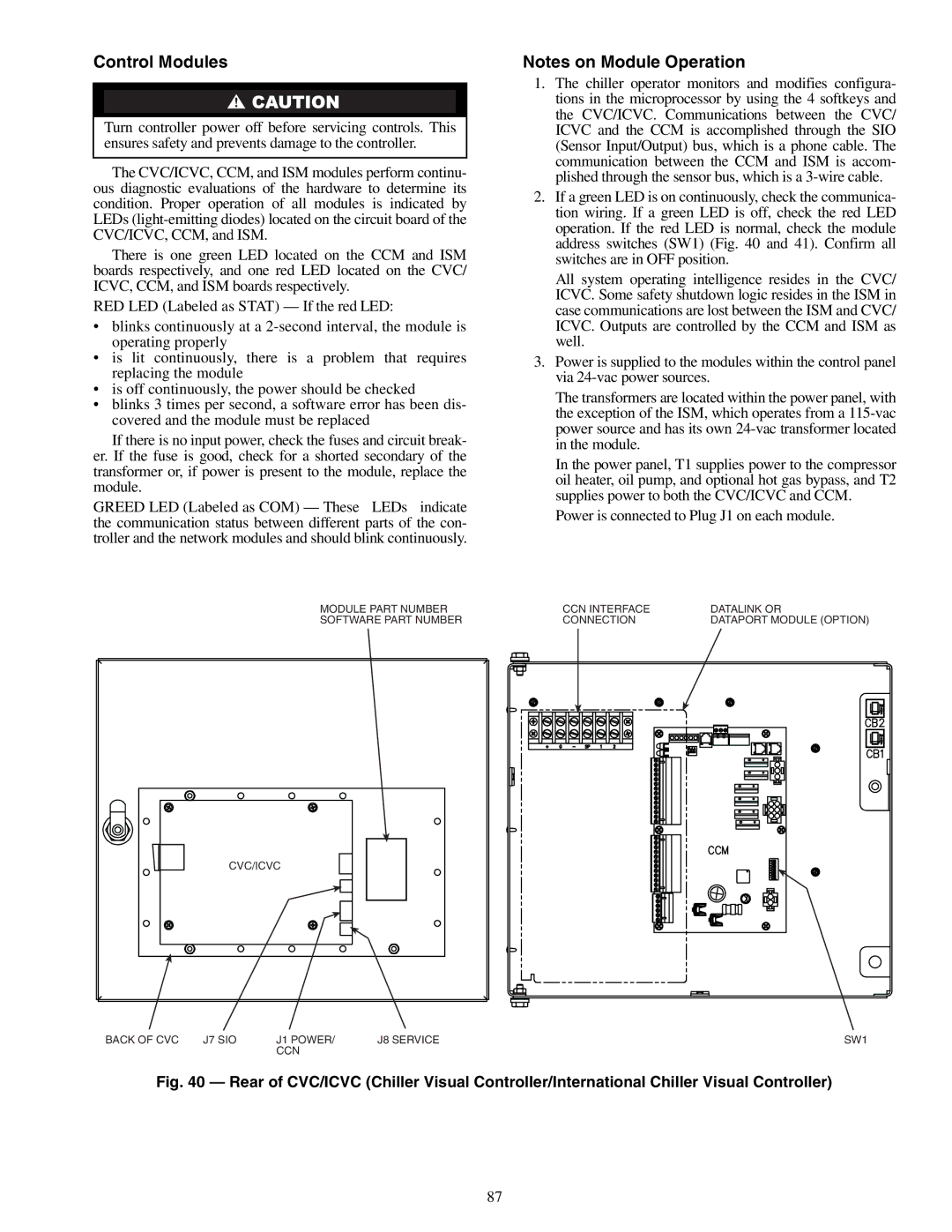
1.The chiller operator monitors and modifies configura- tions in the microprocessor by using the 4 softkeys and the CVC/ICVC. Communications between the CVC/ ICVC and the CCM is accomplished through the SIO (Sensor Input/Output) bus, which is a phone cable. The communication between the CCM and ISM is accom- plished through the sensor bus, which is a 3-wire cable.

2.If a green LED is on continuously, check the communica- tion wiring. If a green LED is off, check the red LED operation. If the red LED is normal, check the module address switches (SW1) (Fig. 40 and 41). Confirm all switches are in OFF position.

All system operating intelligence resides in the CVC/ ICVC. Some safety shutdown logic resides in the ISM in case communications are lost between the ISM and CVC/ ICVC. Outputs are controlled by the CCM and ISM as well.

3.Power is supplied to the modules within the control panel via 24-vac power sources.

The transformers are located within the power panel, with the exception of the ISM, which operates from a 115-vac power source and has its own 24-vac transformer located in the module.

In the power panel, T1 supplies power to the compressor oil heater, oil pump, and optional hot gas bypass, and T2 supplies power to both the CVC/ICVC and CCM.

Power is connected to Plug J1 on each module.

CCN INTERFACE

DATALINK OR

CONNECTION

DATAPORT MODULE (OPTION)

BACK OF CVC

J7 SIO

J1 POWER/

J8 SERVICE

SW1


CCN


Fig. 40 — Rear of CVC/ICVC (Chiller Visual Controller/International Chiller Visual Controller)

87

Page 87
Image 87
Carrier XRV, 19XR specifications Control Modules, Power is connected to Plug J1 on each module

19XR, XRV specifications

The Carrier 19XR and 19XRV chillers are sophisticated cooling solutions that represent the forefront of HVAC technology. Designed for large commercial and industrial applications, these chillers provide exceptional performance, energy efficiency, and reliability, making them ideal for a variety of environments ranging from hospitals to manufacturing facilities.

One of the most significant features of the Carrier 19XR and 19XRV chillers is their advanced scroll compressor technology. These units employ a tandem scroll design that enhances efficiency while minimizing operational noise. This makes them ideal for urban environments where noise restrictions may be in place. Moreover, the compressors are equipped with variable speed drive options in the 19XRV model, which allows for greater energy savings by adjusting cooling output based on real-time demand.

In addition to their advanced compressors, the 19XR and 19XRV units incorporate the Carrier GreenChoice refrigerant, which has a lower global warming potential compared to traditional refrigerants. This innovative choice not only meets regulatory requirements but also contributes to sustainability goals, making these chillers a responsible choice for environmentally conscious organizations.

The units are engineered with a robust heat exchanger design, which enhances heat transfer efficiency and overall system performance. This ensures optimal operation even in extreme conditions. They feature a microprocessor-based control system that allows for precise monitoring and control of the chiller’s performance, enabling operators to make real-time adjustments to maximize energy efficiency.

The Carrier 19XR and 19XRV chillers also prioritize serviceability. The design incorporates easy access to key components, simplifying maintenance procedures and reducing downtime. This focus on maintainability extends the lifespan of the equipment, leading to lower lifecycle costs.

In terms of connectivity, these chillers are equipped with advanced Building Management System (BMS) integration capabilities. This allows for seamless monitoring and control of the chillers using a centralized platform, facilitating energy management and operational optimization.

Overall, the Carrier 19XR and 19XRV chillers stand out in the market for their blend of cutting-edge technology, energy efficiency, and user-friendly features. They are engineered to meet the demanding needs of modern commercial and industrial applications, making them a preferred choice for facility managers seeking reliable cooling solutions.