VFD Cooling System Leak Inspection

1.Check for leaks on the refrigerant cooling flange connec- tions to the VFD enclosure.

2.Check for leaks on all tubing internal to the VFD enclo- sure, the tubing flair connection to the VFD module and the TXV valve.

3.Verify that the VFD refrigerant cooling system TXV valve control bulb is securely inserted into the VFD drive module heat sink.

Power Up Verification

1.Inspect control wiring inside the VFD and verify the in- tegrity of the connections between the integrated starter module (ISM) and the VFD module.

2.Close the control power switch in the VFD enclosure.

3.Close the oil pump power switch inside the VFD enclosure.

4.Verify the VFD disconnect switch is in the open position.

5.Close and latch the doors of the VFD enclosure.

6.Apply power to the VFD enclosure. Remove lock outs and close all disconnects.

7.Verify that the CVC/ICVC display powers up and goes to the default screen.

8.Close the VFD disconnect switch.

9.Verify the following actions during the VFD start-up self test:

The display shows SELF and all LEDs are illumi- nated for 5 to 6 seconds.

The display reads a 0 after the diagnosis is complete.

If Err is displayed a fault has been detected. Perform manual reset by establishing a reset through the small hole under the VFD Keypad. If this does not correct the fault contact your Carrier representative.

If AR with a counting down number is displayed wait for the number to count to 0 and the display should then revert to a 0. If the counter starts over at 30 contact Carrier representative.

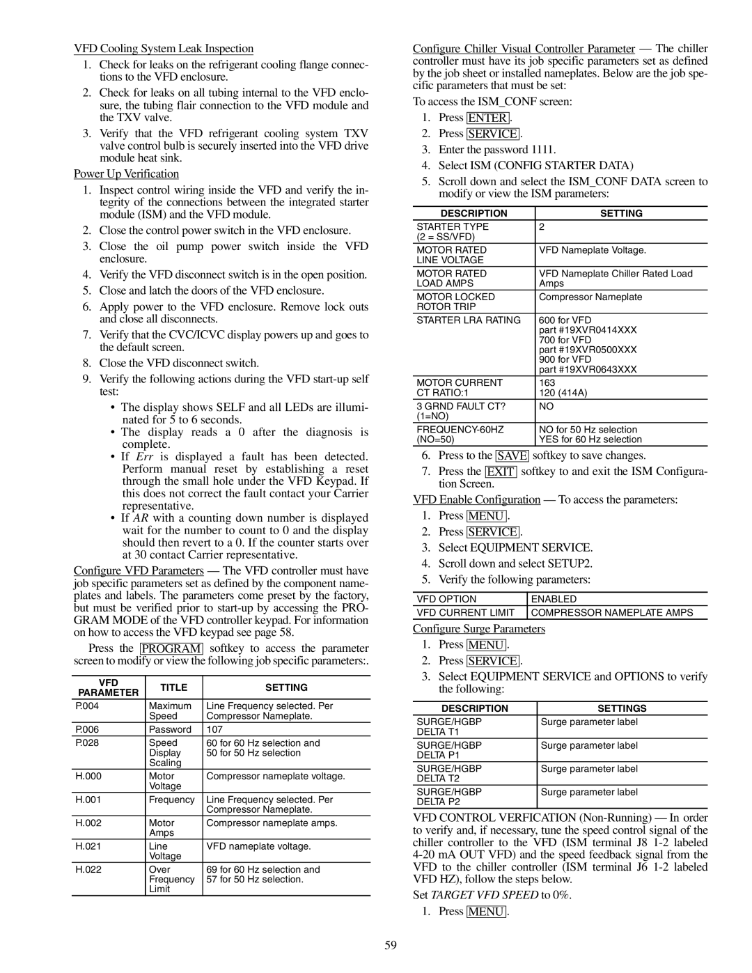
Configure VFD Parameters — The VFD controller must have job specific parameters set as defined by the component name- plates and labels. The parameters come preset by the factory, but must be verified prior to start-up by accessing the PRO- GRAM MODE of the VFD controller keypad. For information on how to access the VFD keypad see page 58.

Press the PROGRAM softkey to access the parameter screen to modify or view the following job specific parameters:.

VFD

TITLE

SETTING

PARAMETER


P.004

Maximum

Line Frequency selected. Per


Speed

Compressor Nameplate.

P.006

Password

107

P.028

Speed

60 for 60 Hz selection and


Display

50 for 50 Hz selection


Scaling


H.000

Motor

Compressor nameplate voltage.


Voltage


H.001

Frequency

Line Frequency selected. Per


Compressor Nameplate.

H.002

Motor

Compressor nameplate amps.


Amps


H.021

Line

VFD nameplate voltage.


Voltage


H.022

Over

69 for 60 Hz selection and


Frequency

57 for 50 Hz selection.


Limit


Configure Chiller Visual Controller Parameter — The chiller controller must have its job specific parameters set as defined by the job sheet or installed nameplates. Below are the job spe- cific parameters that must be set:

To access the ISM_CONF screen:

1.Press ENTER .

2.Press SERVICE .

3.Enter the password 1111.

4.Select ISM (CONFIG STARTER DATA)

5.Scroll down and select the ISM_CONF DATA screen to modify or view the ISM parameters:

DESCRIPTION

SETTING

STARTER TYPE

2

(2 = SS/VFD)


MOTOR RATED

VFD Nameplate Voltage.

LINE VOLTAGE


MOTOR RATED

VFD Nameplate Chiller Rated Load

LOAD AMPS

Amps

MOTOR LOCKED

Compressor Nameplate

ROTOR TRIP


STARTER LRA RATING

600 for VFD


part #19XVR0414XXX


700 for VFD


part #19XVR0500XXX


900 for VFD


part #19XVR0643XXX

MOTOR CURRENT

163

CT RATIO:1

120 (414A)

3 GRND FAULT CT?

NO

(1=NO)


FREQUENCY-60HZ

NO for 50 Hz selection

(NO=50)

YES for 60 Hz selection

6.Press to the SAVE softkey to save changes.

7.Press the EXIT softkey to and exit the ISM Configura- tion Screen.

VFD Enable Configuration — To access the parameters:

1.Press MENU .

2.Press SERVICE .

3.Select EQUIPMENT SERVICE.

4.Scroll down and select SETUP2.

5.Verify the following parameters:

VFD OPTION

ENABLED

VFD CURRENT LIMIT

COMPRESSOR NAMEPLATE AMPS

Configure Surge Parameters

1.Press MENU .

2.Press SERVICE .

3.Select EQUIPMENT SERVICE and OPTIONS to verify the following:

DESCRIPTION

SETTINGS

SURGE/HGBP

Surge parameter label

DELTA T1


SURGE/HGBP

Surge parameter label

DELTA P1


SURGE/HGBP

Surge parameter label

DELTA T2


SURGE/HGBP

Surge parameter label

DELTA P2


VFD CONTROL VERFICATION (Non-Running) — In order to verify and, if necessary, tune the speed control signal of the chiller controller to the VFD (ISM terminal J8 1-2 labeled 4-20 mA OUT VFD) and the speed feedback signal from the VFD to the chiller controller (ISM terminal J6 1-2 labeled VFD HZ), follow the steps below.

Set TARGET VFD SPEED to 0%.

1. Press MENU .

59

Page 59
Image 59
Carrier XRV, 19XR specifications VFD Title Setting Parameter, Description Settings

19XR, XRV specifications

The Carrier 19XR and 19XRV chillers are sophisticated cooling solutions that represent the forefront of HVAC technology. Designed for large commercial and industrial applications, these chillers provide exceptional performance, energy efficiency, and reliability, making them ideal for a variety of environments ranging from hospitals to manufacturing facilities.

One of the most significant features of the Carrier 19XR and 19XRV chillers is their advanced scroll compressor technology. These units employ a tandem scroll design that enhances efficiency while minimizing operational noise. This makes them ideal for urban environments where noise restrictions may be in place. Moreover, the compressors are equipped with variable speed drive options in the 19XRV model, which allows for greater energy savings by adjusting cooling output based on real-time demand.

In addition to their advanced compressors, the 19XR and 19XRV units incorporate the Carrier GreenChoice refrigerant, which has a lower global warming potential compared to traditional refrigerants. This innovative choice not only meets regulatory requirements but also contributes to sustainability goals, making these chillers a responsible choice for environmentally conscious organizations.

The units are engineered with a robust heat exchanger design, which enhances heat transfer efficiency and overall system performance. This ensures optimal operation even in extreme conditions. They feature a microprocessor-based control system that allows for precise monitoring and control of the chiller’s performance, enabling operators to make real-time adjustments to maximize energy efficiency.

The Carrier 19XR and 19XRV chillers also prioritize serviceability. The design incorporates easy access to key components, simplifying maintenance procedures and reducing downtime. This focus on maintainability extends the lifespan of the equipment, leading to lower lifecycle costs.

In terms of connectivity, these chillers are equipped with advanced Building Management System (BMS) integration capabilities. This allows for seamless monitoring and control of the chillers using a centralized platform, facilitating energy management and operational optimization.

Overall, the Carrier 19XR and 19XRV chillers stand out in the market for their blend of cutting-edge technology, energy efficiency, and user-friendly features. They are engineered to meet the demanding needs of modern commercial and industrial applications, making them a preferred choice for facility managers seeking reliable cooling solutions.