Protecting the VFD Configuration
1.Select parameter P.051 from the VFD keypad.
2.Press the ENTER softkey to access the parameter. A zero will be displayed.
3.Use the ↑ arrow key to increment the value to 26. This is the password number.
4.Press the ENTER softkey to save the value. P.051 will by displayed.
NOTE: Parameter programming is disabled when the PASSWORD LED is on and enabled when the PASS- WORD LED is off.
5.Select parameter P.006 from the VFD Keypad.
6.Press the ENTER softkey to access the parameter.
7.Use the ↑ arrow key to increment the value to 107. This is the password number to restrict displaying the remain- ing P, and all of the H and r parameters.
8.Press the ENTER softkey to save the value.
Modify Minimum and Maximum Load Points (∆T1/P1; ∆T2/ P2) If Necessary — These pairs of chiller load points, located on the OPTIONS screen, determine when to limit guide vane travel or open the hot gas bypass valve when surge prevention is needed. These points should be set based on individual chiller operating conditions.
A label that lists the configuration values of the controls is located on the inside of the unit’s control panel. These values are based upon the original selection of the chiller. Jobsite con- ditions may require a slight modification to these parameters.
If after configuring a value for these points, surge preven- tion is operating too soon or too late for conditions, these pa- rameters should be changed by the operator.
An example of such a configuration is shown below. Refrigerant: HCFC-134a
Estimated Minimum Load Conditions:
44 F (6.7 C) LCW
45.5 F (7.5 C) ECW
43 F (6.1 C) Suction Temperature
70 F (21.1 C) Condensing Temperature
Estimated Maximum Load Conditions:
44 F (6.7 C) LCW
54 F (12.2 C) ECW
42 F (5.6 C) Suction Temperature
98 F (36.7 C) Condensing Temperature
Calculate Maximum Load — To calculate the maximum load points, use the design load condition data. If the chiller full load cooler temperature difference is more than 15 F (8.3 C), esti- mate the refrigerant suction and condensing temperatures at this difference. Use the proper saturated pressure and tempera- ture for the particular refrigerant used.
Suction Temperature:
42 F (5.6 C) = 37 psig (255 kPa) saturated refrigerant pressure (HFC-134a)
Condensing Temperature:
98 F (36.7 C) = 120 psig (1827 kPa) saturated refrigerant pressure (HFC-134a)
Maximum Load ∆T2:
54 – 44 = 10º F (12.2 – 6.7 = 5.5º C) Maximum Load ∆P2:
120 – 37 = 83 psid (827 – 255 = 572 kPad)
To avoid unnecessary surge prevention, add about 10 psid
(70 kPad) to ∆P2 from these conditions:
∆T2 = 10º F (5.5º C)
∆P2 = 93 psid (642 kPad)
Calculate Minimum Load — To calculate the minimum load conditions, estimate the temperature difference the cooler will have at 10% load, then estimate what the suction and condens- ing temperatures will be at this point. Use the proper saturated pressure and temperature for the particular refrigerant used.
Suction Temperature:
43 F (6.1 C) = 38 psig (262 kPa) saturated refrigerant pressure (HFC-134a)
Condensing Temperature:
70 F (21.1 C) = 71 psig (490 kPa) saturated refrigerant pressure (HFC-134a)
Minimum Load ∆T1 (at 20% Load): 2 F (1.1 C) Minimum Load ∆P1:
71 – 38 = 33 psid (490 – 262 = 228 kPad)
Again, to avoid unnecessary surge prevention, add 20 psid
(140 kPad) at ∆P1 from these conditions: ∆T1 = 2 F (1.1 C)
∆P1 = 53 psid (368 kPad)
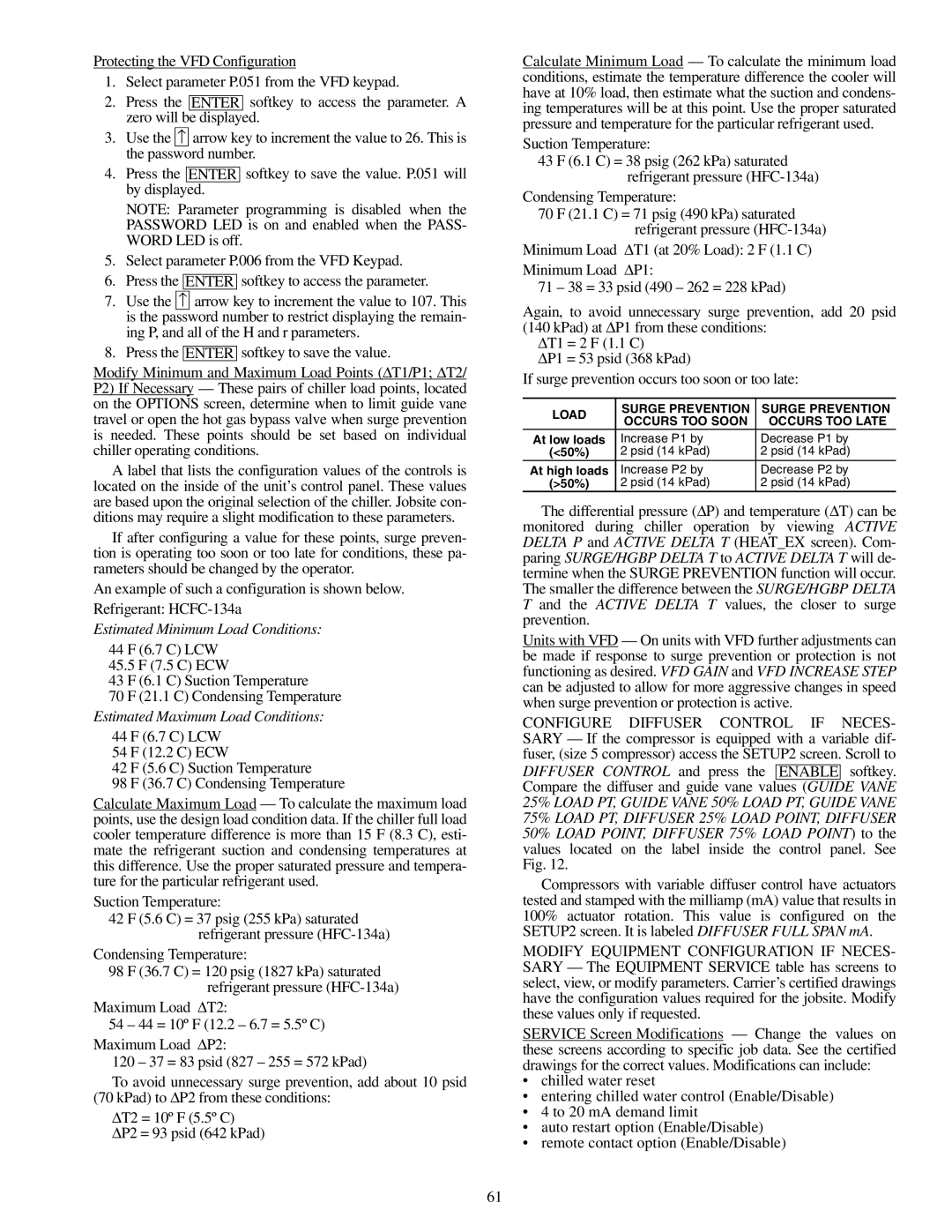
If surge prevention occurs too soon or too late:
| LOAD | SURGE PREVENTION | SURGE PREVENTION |
| OCCURS TOO SOON | OCCURS TOO LATE |
| |
| At low loads | Increase P1 by | Decrease P1 by |
| (<50%) | 2 psid (14 kPad) | 2 psid (14 kPad) |
| At high loads | Increase P2 by | Decrease P2 by |
| (>50%) | 2 psid (14 kPad) | 2 psid (14 kPad) |
The differential pressure (∆P) and temperature (∆T) can be monitored during chiller operation by viewing ACTIVE DELTA P and ACTIVE DELTA T (HEAT_EX screen). Com- paring SURGE/HGBP DELTA T to ACTIVE DELTA T will de- termine when the SURGE PREVENTION function will occur. The smaller the difference between the SURGE/HGBP DELTA T and the ACTIVE DELTA T values, the closer to surge prevention.
Units with VFD — On units with VFD further adjustments can be made if response to surge prevention or protection is not functioning as desired. VFD GAIN and VFD INCREASE STEP can be adjusted to allow for more aggressive changes in speed when surge prevention or protection is active.
CONFIGURE DIFFUSER CONTROL IF NECES- SARY — If the compressor is equipped with a variable dif- fuser, (size 5 compressor) access the SETUP2 screen. Scroll to
DIFFUSER CONTROL and press the ENABLE softkey. Compare the diffuser and guide vane values (GUIDE VANE 25% LOAD PT, GUIDE VANE 50% LOAD PT, GUIDE VANE 75% LOAD PT, DIFFUSER 25% LOAD POINT, DIFFUSER 50% LOAD POINT, DIFFUSER 75% LOAD POINT) to the values located on the label inside the control panel. See Fig. 12.
Compressors with variable diffuser control have actuators tested and stamped with the milliamp (mA) value that results in 100% actuator rotation. This value is configured on the SETUP2 screen. It is labeled DIFFUSER FULL SPAN mA.
MODIFY EQUIPMENT CONFIGURATION IF NECES- SARY — The EQUIPMENT SERVICE table has screens to select, view, or modify parameters. Carrier’s certified drawings have the configuration values required for the jobsite. Modify these values only if requested.
SERVICE Screen Modifications — Change the values on these screens according to specific job data. See the certified drawings for the correct values. Modifications can include:
•chilled water reset
•entering chilled water control (Enable/Disable)
•4 to 20 mA demand limit
•auto restart option (Enable/Disable)
•remote contact option (Enable/Disable)