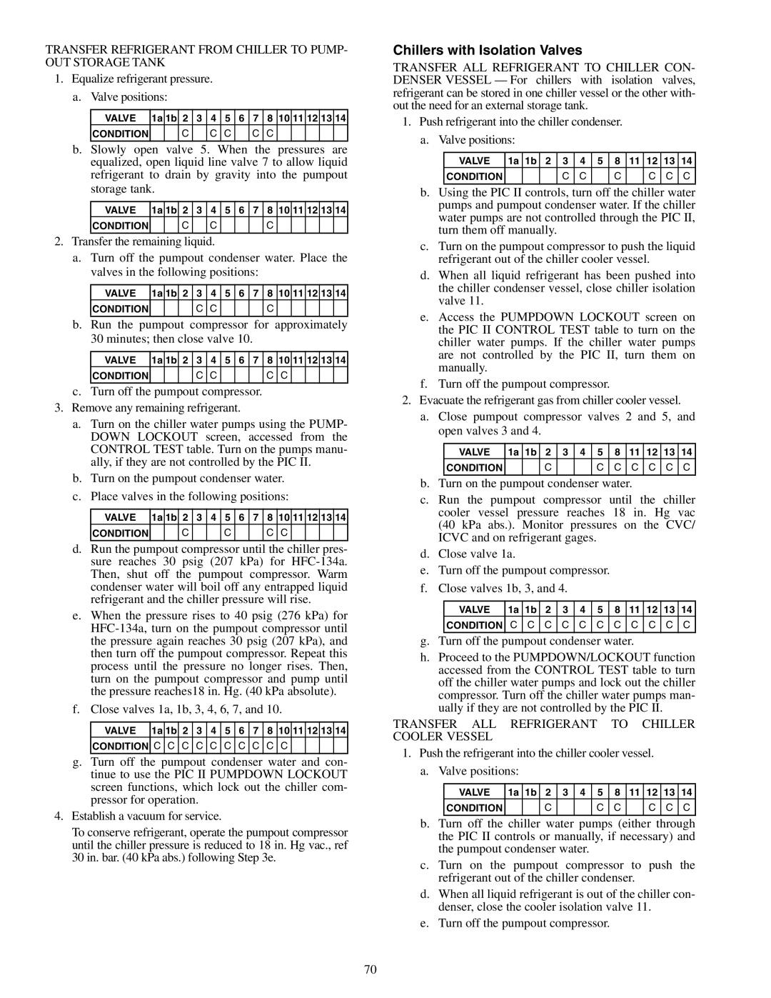
Carrier 19XR, XRV Chillers with Isolation Valves, Push refrigerant into the chiller condenser

Models: 19XR XRV

1 140
Download 140 pages 13.24 Kb
Page 70
Image 70

TRANSFER REFRIGERANT FROM CHILLER TO PUMP- OUT STORAGE TANK

1. Equalize refrigerant pressure.


a.

Valve positions:


VALVE

1a

1b

2

3

4

5

6

7

8

10

11

12

13

14


CONDITION


C


C

C


C

C


b.

Slowly open valve 5. When the pressures are


equalized, open liquid line valve 7 to allow liquid


refrigerant to drain by gravity into the pumpout


storage tank.


VALVE

1a

1b

2

3

4

5

6

7

8

10

11

12

13

14


CONDITION


C


C


C


2. Transfer the remaining liquid.


a.

Turn off the pumpout condenser water. Place the


valves in the following positions:


VALVE

1a

1b

2

3

4

5

6

7

8

10

11

12

13

14


CONDITION


C

C


C


b.

Run the pumpout compressor for approximately


30 minutes; then close valve 10.


VALVE

1a

1b

2

3

4

5

6

7

8

10

11

12

13

14


CONDITION


C

C


C

C


c.

Turn off the pumpout compressor.


3. Remove any remaining refrigerant.


a.

Turn on the chiller water pumps using the PUMP-


DOWN LOCKOUT screen, accessed from the


CONTROL TEST table. Turn on the pumps manu-


ally, if they are not controlled by the PIC II.

b.

Turn on the pumpout condenser water.

c.

Place valves in the following positions:


VALVE

1a

1b

2

3

4

5

6

7

8

10

11

12

13

14


CONDITION


C


C


C

C


d.

Run the pumpout compressor until the chiller pres-


sure reaches 30 psig (207 kPa) for HFC-134a.


Then, shut off the pumpout compressor. Warm


condenser water will boil off any entrapped liquid


refrigerant and the chiller pressure will rise.

e.

When the pressure rises to 40 psig (276 kPa) for


HFC-134a, turn on the pumpout compressor until


the pressure again reaches 30 psig (207 kPa), and


then turn off the pumpout compressor. Repeat this


process until the pressure no longer rises. Then,


turn on the pumpout compressor and pump until


the pressure reaches18 in. Hg. (40 kPa absolute).

f.

Close valves 1a, 1b, 3, 4, 6, 7, and 10.


VALVE

1a

1b

2

3

4

5

6

7

8

10

11

12

13

14


CONDITION

C

C

C

C

C

C

C

C

C

C


g.Turn off the pumpout condenser water and con- tinue to use the PIC II PUMPDOWN LOCKOUT screen functions, which lock out the chiller com- pressor for operation.

4.Establish a vacuum for service.

To conserve refrigerant, operate the pumpout compressor until the chiller pressure is reduced to 18 in. Hg vac., ref 30 in. bar. (40 kPa abs.) following Step 3e.

Chillers with Isolation Valves

TRANSFER ALL REFRIGERANT TO CHILLER CON- DENSER VESSEL — For chillers with isolation valves, refrigerant can be stored in one chiller vessel or the other with- out the need for an external storage tank.

1. Push refrigerant into the chiller condenser.


a.

Valve positions:


VALVE

1a

1b


2

3

4

5


8

11

12


13


14


CONDITION


C

C


C


C


C


C

b.

Using the PIC II controls, turn off the chiller water


pumps and pumpout condenser water. If the chiller


water pumps are not controlled through the PIC II,


turn them off manually.


c.

Turn on the pumpout compressor to push the liquid


refrigerant out of the chiller cooler vessel.


d.

When all liquid refrigerant has been pushed into


the chiller condenser vessel, close chiller isolation


valve 11.


e. Access the PUMPDOWN LOCKOUT screen on


the PIC II CONTROL TEST table to turn on the


chiller water pumps. If the chiller water pumps


are not controlled by the PIC II, turn them on


manually.


f.

Turn off the pumpout compressor.


2. Evacuate the refrigerant gas from chiller cooler vessel.


a.

Close pumpout compressor valves 2 and 5, and


open valves 3 and 4.


VALVE

1a

1b


2

3

4

5


8

11

12


13


14


CONDITION


C


C


C

C

C


C


C

b.

Turn on the pumpout condenser water.


c.

Run the pumpout compressor until the chiller


cooler vessel pressure reaches 18 in. Hg vac


(40 kPa abs.). Monitor pressures on the CVC/


ICVC and on refrigerant gages.


d.

Close valve 1a.


e.

Turn off the pumpout compressor.


f.

Close valves 1b, 3, and 4.


VALVE

1a

1b


2

3

4

5


8

11

12


13


14


CONDITION

C

C

C

C

C

C


C

C

C


C


C

g.

Turn off the pumpout condenser water.


h. Proceed to the PUMPDOWN/LOCKOUT function


accessed from the CONTROL TEST table to turn


off the chiller water pumps and lock out the chiller


compressor. Turn off the chiller water pumps man-


ually if they are not controlled by the PIC II.


TRANSFER ALL REFRIGERANT TO CHILLER

COOLER VESSEL


1. Push the refrigerant into the chiller cooler vessel.


a.

Valve positions:


VALVE

1a

1b


2

3

4

5


8

11

12


13


14


CONDITION


C


C


C


C


C


C

b.

Turn off the chiller water pumps (either through


the PIC II controls or manually, if necessary) and


the pumpout condenser water.


c.

Turn on the pumpout compressor to push the


refrigerant out of the chiller condenser.


d.

When all liquid refrigerant is out of the chiller con-


denser, close the cooler isolation valve 11.


e.

Turn off the pumpout compressor.


70

Page 70
Image 70
Carrier 19XR, XRV specifications Chillers with Isolation Valves, Push refrigerant into the chiller condenser