19XR, XRV specifications
The Carrier 19XR and 19XRV chillers are sophisticated cooling solutions that represent the forefront of HVAC technology. Designed for large commercial and industrial applications, these chillers provide exceptional performance, energy efficiency, and reliability, making them ideal for a variety of environments ranging from hospitals to manufacturing facilities.One of the most significant features of the Carrier 19XR and 19XRV chillers is their advanced scroll compressor technology. These units employ a tandem scroll design that enhances efficiency while minimizing operational noise. This makes them ideal for urban environments where noise restrictions may be in place. Moreover, the compressors are equipped with variable speed drive options in the 19XRV model, which allows for greater energy savings by adjusting cooling output based on real-time demand.
In addition to their advanced compressors, the 19XR and 19XRV units incorporate the Carrier GreenChoice refrigerant, which has a lower global warming potential compared to traditional refrigerants. This innovative choice not only meets regulatory requirements but also contributes to sustainability goals, making these chillers a responsible choice for environmentally conscious organizations.
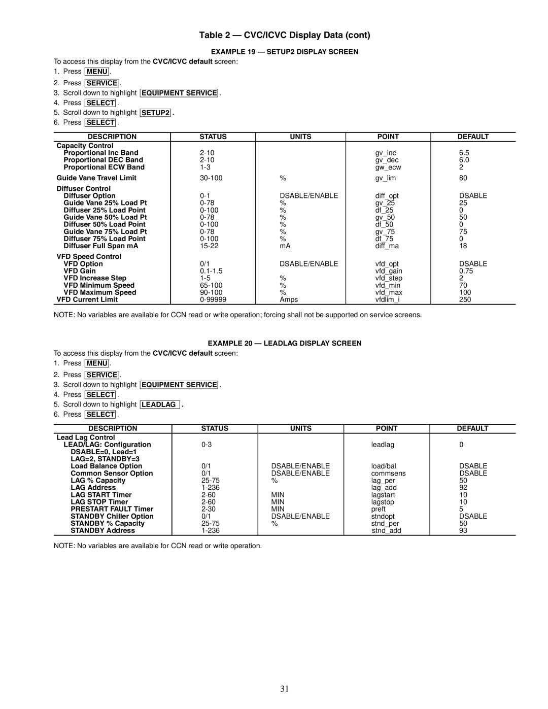
The units are engineered with a robust heat exchanger design, which enhances heat transfer efficiency and overall system performance. This ensures optimal operation even in extreme conditions. They feature a microprocessor-based control system that allows for precise monitoring and control of the chiller’s performance, enabling operators to make real-time adjustments to maximize energy efficiency.
The Carrier 19XR and 19XRV chillers also prioritize serviceability. The design incorporates easy access to key components, simplifying maintenance procedures and reducing downtime. This focus on maintainability extends the lifespan of the equipment, leading to lower lifecycle costs.
In terms of connectivity, these chillers are equipped with advanced Building Management System (BMS) integration capabilities. This allows for seamless monitoring and control of the chillers using a centralized platform, facilitating energy management and operational optimization.
Overall, the Carrier 19XR and 19XRV chillers stand out in the market for their blend of cutting-edge technology, energy efficiency, and user-friendly features. They are engineered to meet the demanding needs of modern commercial and industrial applications, making them a preferred choice for facility managers seeking reliable cooling solutions.

