Appendix A Reference
Cable and Adapter Specifications
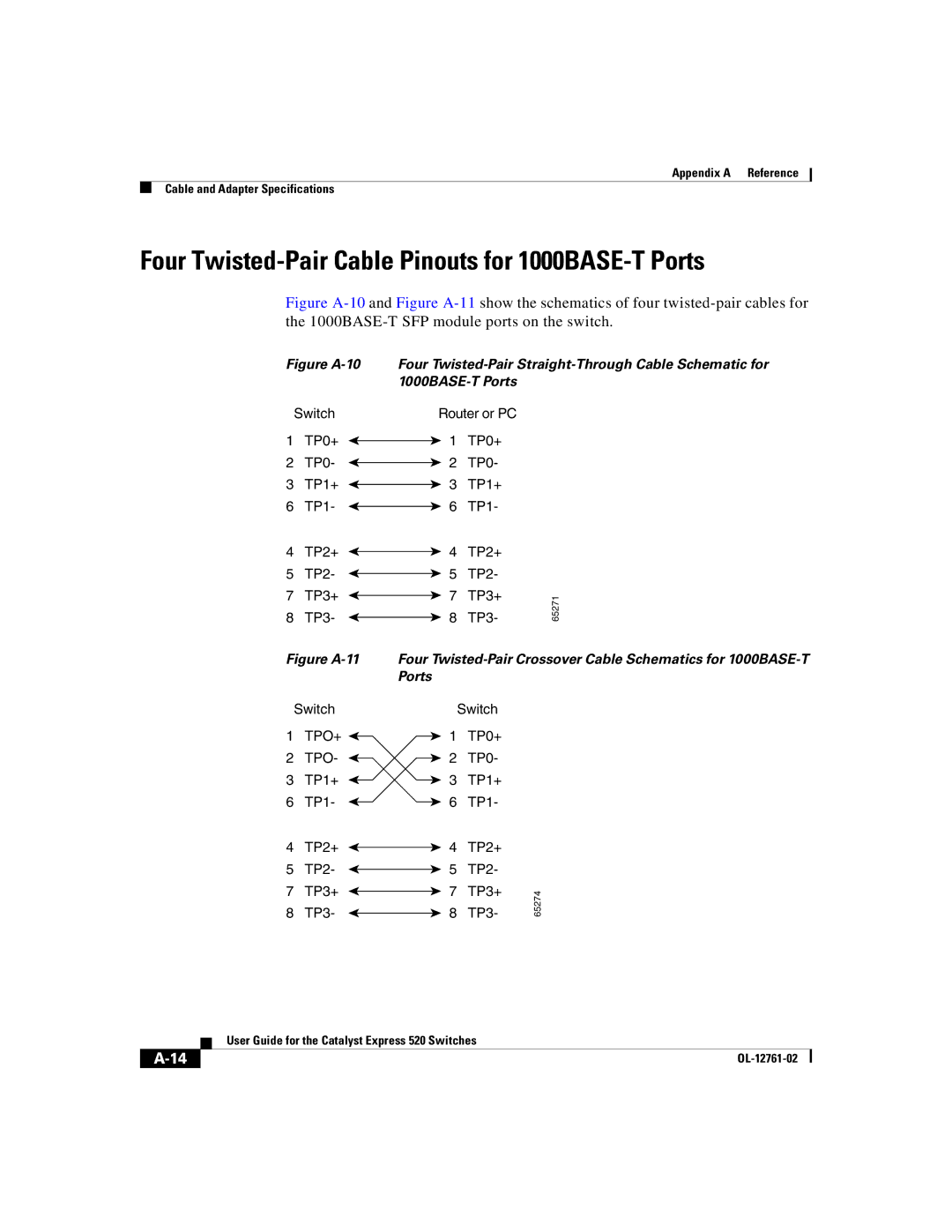
Four Twisted-Pair Cable Pinouts for 1000BASE-T Ports
Figure A-10 and Figure A-11 show the schematics of four twisted-pair cables for the 1000BASE-T SFP module ports on the switch.
Figure A-10
Switch
1 TP0+
2 TP0-
3 TP1+
6 TP1-
4 TP2+
5 TP2-
7 TP3+
8 TP3-
Figure A-11
Switch
1TPO+ ![]()
2TPO- ![]()
3TP1+ ![]()
6TP1- ![]()
4TP2+ ![]()
5TP2- ![]()
7TP3+ ![]()
8TP3- ![]()
Four
Router or PC
1 TP0+
2 TP0-
3 TP1+
6 TP1-
4 | TP2+ |
| |
5 | TP2- |
| |
7 | TP3+ | 65271 | |
8 | TP3- | ||
|
Four
| Switch |
| |
1 | TP0+ |
| |
2 | TP0- |
| |
3 | TP1+ |
| |
6 | TP1- |
| |
4 | TP2+ |
| |
5 | TP2- |
| |
7 | TP3+ | 65274 | |
8 | TP3- | ||
|
| User Guide for the Catalyst Express 520 Switches |
|