Cisco Systems 520 manual Connector Specifications

Models: 520

1 114
Download 114 pages 29.31 Kb
Page 91
Image 91

Appendix A Reference

Connector Specifications

Connector Specifications

This section describes the connectors on the switch.

10/100 and 10/100/1000 Ports, page A-5

SFP Module Ports, page A-8

Dual-Purpose Ports, page A-9

10/100 and 10/100/1000 Ports

The 10/100 and 10/100/1000 Ethernet ports use standard RJ-45 connectors and Ethernet pinouts with internal crossovers. These ports have the send (TD) and receive (RD) signals internally crossed so that a twisted-pair straight-through cable and adapter can be attached to the port. Figure A-3shows the pinout for a 10/100 port.

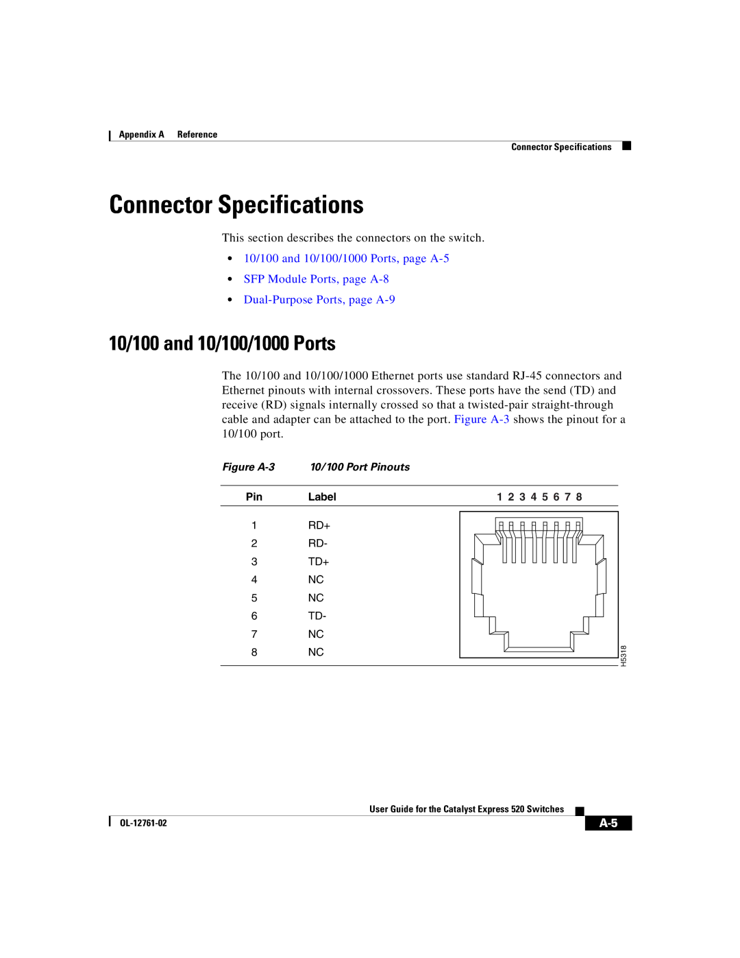
Figure A-3 10/100 Port Pinouts

Pin Label

1RD+

2RD-

3TD+

4NC

5NC

6TD-

7NC

8NC

1 2 3 4 5 6 7 8

H5 183


User Guide for the Catalyst Express 520 Switches


OL-12761-02


A-5


Page 91
Image 91
Cisco Systems 520 manual Connector Specifications