Chapter 1 Introduction
Hardware Features
Hardware Features
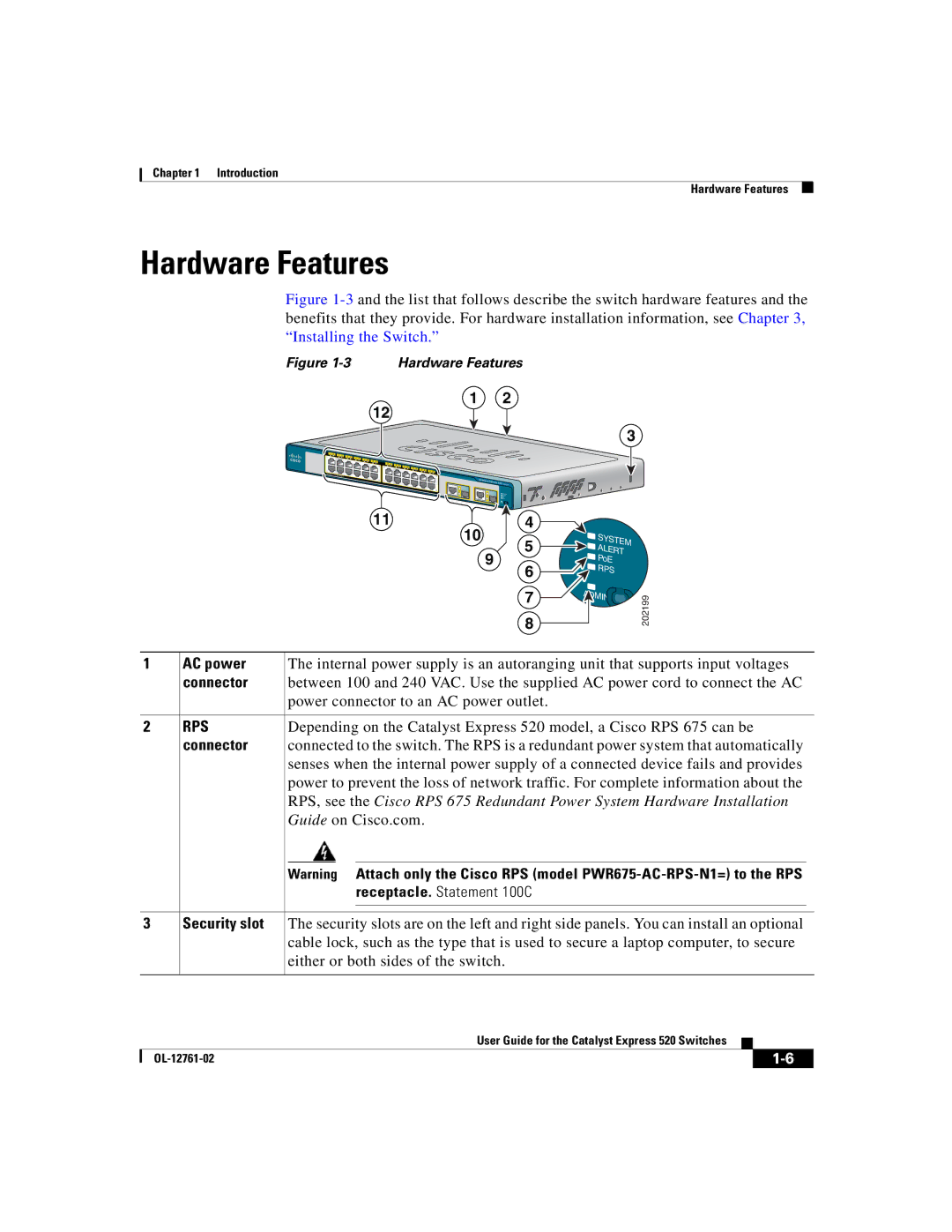
Figure 1-3 and the list that follows describe the switch hardware features and the benefits that they provide. For hardware installation information, see Chapter 3, “Installing the Switch.”
Figure 1-3 Hardware Features
12
1 | 2 | 3 | 4 | 5 |
|
|
|
|
|
|
|
|
|
|
|
|
|
|
|
|
|
|
|
1 |
|
| 6 | 7 | 8 |
|
|
|
|
|
|
|
|
|
|
|
|
|
|
|
| ||
|
|
|
|
|
| 9 | 10 | 11 |
|
|
|
|
|
|
|
|
|
|
|
|
| ||
|
|
|
|
|
|
|
|
| 12 |
|
|
|
|
|
|
|
|
|
|
|
| ||
|
|
|
|
|
|
|
|
|
|
| 11 | 13 | 14 | 15 | 16 | 17 |
|
|
|
|
|
|
|
|
|
|
|
|
|
|
|
|
|
| 13 |
|
| 18 | 19 | 20 |
|
|
|
| |||
2 |
|
|
|
|
|
|
|
|
|
|
|
|
|
|
|
|
| 21 | 22 | 23 |
| ||
|
|
|
|
|
|
|
|
|
|
|
|
|
|
|
|
|
|
|
| 24 | |||
POWER |
| ETHERNET |
|
|
|
|
|
|
|
|
|
|
|
|
|
|
|
|
|
|
| 23 | |
|
|
|
|
|
|
|
|
|
|
|
|
|
|
|
|
|
|
|
|
| |||
1214
24
11
1 |
| 2 |
|
|
|
| 3 |
| Catalyst |
|
|
| Express |
| |
|
| 520 Series |
|
1 |
|
|
|
| 2 |
|
|
10 | 4 |
| |
| SYS | ||
|
| 5 | TEM |
| 9 | ALERT | |
| 6 | PoE | |
|
| RPS | |
|
|
| |
7 | IN | 202199 |
| ||
8 |
| |
|
|
1 |
| AC power |
| The internal power supply is an autoranging unit that supports input voltages | |||||
|
| connector |
| between 100 and 240 VAC. Use the supplied AC power cord to connect the AC | |||||
|
|
|
| power connector to an AC power outlet. | |||||
|
|
|
|
| |||||
2 |
| RPS |
| Depending on the Catalyst Express 520 model, a Cisco RPS 675 can be | |||||
|
| connector |
| connected to the switch. The RPS is a redundant power system that automatically | |||||
|
|
|
| senses when the internal power supply of a connected device fails and provides | |||||
|
|
|
| power to prevent the loss of network traffic. For complete information about the | |||||
|
|
|
| RPS, see the Cisco RPS 675 Redundant Power System Hardware Installation | |||||
|
|
|
| Guide on Cisco.com. | |||||
|
|
|
|
|
|
|
| ||
|
|
|
| Warning Attach only the Cisco RPS (model | |||||
|
|
|
|
|
| receptacle. Statement 100C | |||
|
|
|
|
|
|
| |||
|
|
|
|
| |||||
3 |
| Security slot |
| The security slots are on the left and right side panels. You can install an optional | |||||
|
|
|
| cable lock, such as the type that is used to secure a laptop computer, to secure | |||||
|
|
|
| either or both sides of the switch. | |||||
|
|
|
|
|
|
|
|
|
|
|
|
|
|
|
| User Guide for the Catalyst Express 520 Switches |
|
|
|
|
|
|
|
| |||||
|
|
|
|
|
| ||||
|
|
|
|
| |||||
